


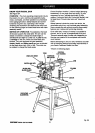
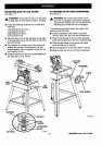
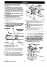
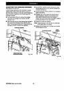
SETTING THE ARM LOCK KNOB
See Figure 16.
It may be possible to move the arm when locked, if
the arm lock knob is too loose. If the arm does not
move freely when unlocked, the arm lock knob may
be too tight. Use this procedure to chec.k and set the
arm lock knob by turning the arm lock wheel (under
the carriage arm).
• Release the arm lock knob, located on top of the
arm at the front.
• Swing the arm 30" to the left or the right, referring
to the miter scale on top ofthe column.
• Lock the arm in place with the arm lock knob.
• Apply a reasonable amount of pressure. The arm
can be forced but if it moves easily, it needs
adjustment.
• Locate the arm lock wheel.
• Release the arm lock knob and turn the lock wheel
clockwise to tighten or counterclockwise to loosen.
• Repeat above steps untilthe arm movement is
minimized when locked.
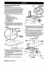
ARM LOCK KNOB ARM
TURNCOUNTERCLOCK-
WISETOLOOSEN
CARRIAGE TURNCLOCKWISE
STOPSCREW ARM TO TIGHTEN
LOCKWHEEL Fig. 16
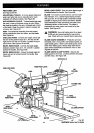
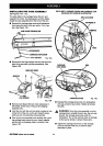
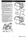
SETTING THE YOKE CLAMP
See Figures 17A and 17B.
The yoke clamp keeps the yoke from rotating on the
carriage when you want the saw blade to be station-
ary. Use this procedure to check and set the yoke
clamp.
• Release the yoke lock handle (below the arm on
the right side) so the motor can be rotated.
• Swivel the motor slightly. It should be at an angle in
between one of the preset positive stop angles.
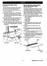
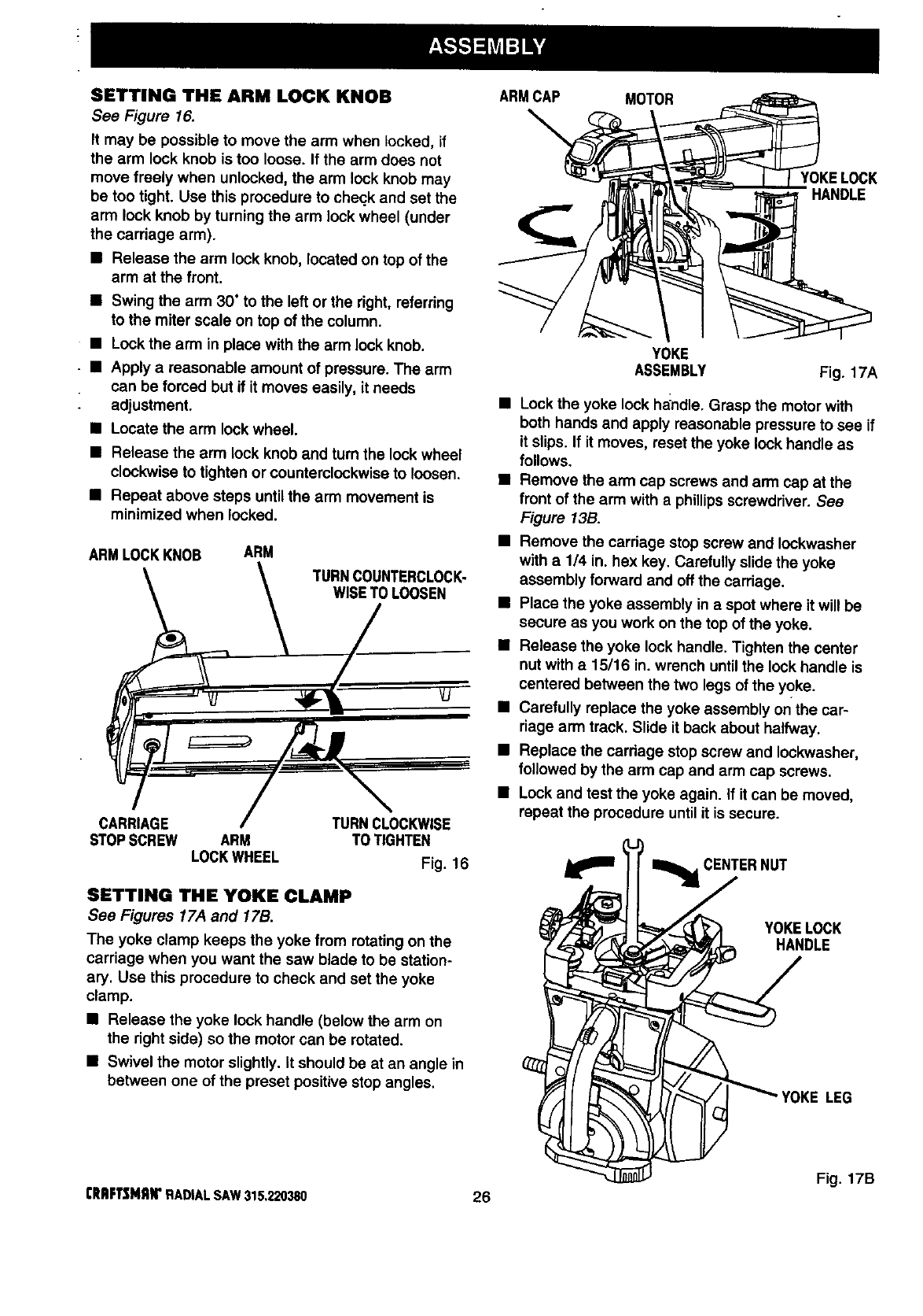
ARMCAP MOTOR
YOKELOCK
HANDLE
YOKE
ASSEMBLY Fig. 17A
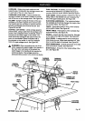
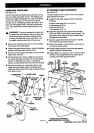
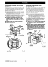
• Lock the yoke lock handle. Grasp the motor with
both hands and apply reasonable pressure to see if
it slips. If it moves, reset the yoke lock handle as
follows.
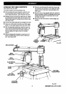
• Remove the arm cap screws and arm cap at the
front of the arm with a phillips screwdriver. See
Figure 13B.
• Remove the carriage stop screw and Iockwasher
with a 1/4 in. hex key. Carefully slide the yoke
assembly forward and off the carriage.
• Place the yoke assembly in a spot where it will be
secure as you work on the top of the yoke,
• Release the yoke lock handle. Tighten the center
nut with a 15/16 in. wrench until the lock handle is
centered between the two legs of the yoke.
• Carefully replace the yoke assembly on the car-
riage arm track. Slide it back about halfway.
• Replace the cardage stop screw and Iockwasher,
followed by the arm cap and arm cap screws.
• Lock and test the yoke again. If it can be moved,
repeat the procedure until it is secure.
I_I_CENTER NUT
YOKELOCK
HANDLE
LEG
Fig. 17B
[RAFTSMAN"RADIALSAW315.220380 26