


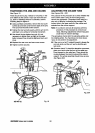
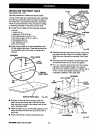
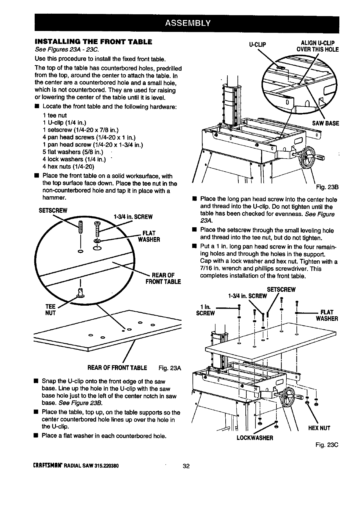
INSTALLING THE FRONT TABLE
See Figures 23A - 23C.
Use this procedure to install the fixed front table.
The top of the table has counterbored holes, predrilled
from the top, around the center to attach the table. In
the center are a counterbored hole and a small hole,
which is not counterbored. They are used for raising
or lowering the center of the table until it is level.
• Locate the front table and the following hardware:
1 tee nut
1 U-clip (1/4 in.)
1 setscrew (1/4-20 x 7/8 in.)
4 pan head screws (1/4-20 x 1 in.)
1 pan head screw (1/4-20 x 1-3/4 in.)
5 flat washers (5/8 in.)
4 lock washers (1/4 in.) "
4 hex nuts (1/4-20)
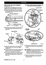
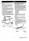
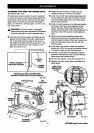
• Place the front table on a solid worksurface, with
the top surface face down. Place the tee nut in the
non-counterbored hole and tap it in place with a
hammer.
SETSCREW
1-3/4In. SCREW
FLAT
16
FRONTTABLE
TEE
NUT
REAROF FRONTTABLE Fig. 23A
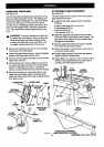
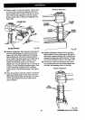
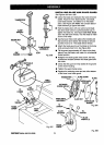
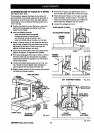
• Snap the U-clip onto the front edge of the saw
base. Line up the hole in the U-clip with the saw
base hole just to the left of the center notch in saw
base. See Figure 23B.
• Place the table, top up, on the table supports so the
center counterbored hole lines up over the hole in
the U-clip.
• Place a flat washer in each counterbored hole.
U-CLIP ALIGNU-CLIP
OVERTHISHOLE
SAWBASE
Fig. 23B
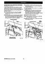
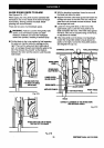
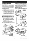
Place the long pan head screw into the center hole
and thread into the U-clip. Do not tighten untilthe
table has been checked for evenness. See Figure
23A.
• Place the setscrew through the small leveling hole
and thread intothe tee nut, but do not tighten.
• Put a 1 in. long pan head screw in the four remain-
ing holes and through the holes in the support.
Cap with a lock washer and hex nut. Tighten with a
7/16 in. wrench and phillips screwdriver. This
completes installation ofthe front table.
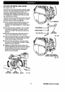
SETSCREW
1-3/4in.SCREW/_
1,,. /., T
SCREW / _1 J[ ' ! FLAT
I , i i WASHER
I
LOCKWASHER
HEXNUT
Fig. 23C
I:RRFTSMRIrRADIALSAW 315.220380 32