


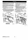
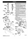
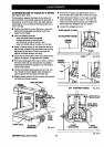
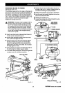
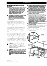
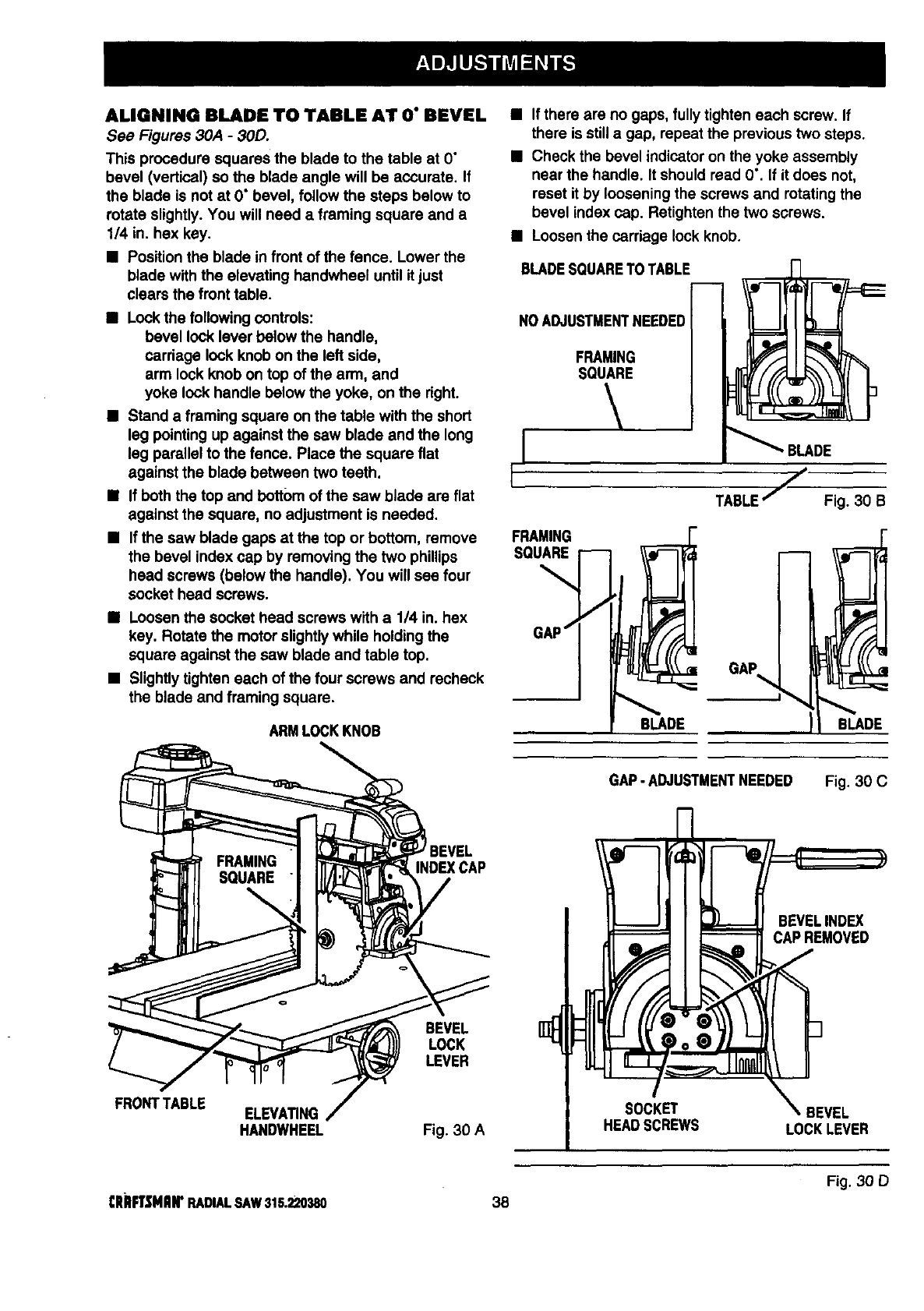
ALIGNING BLADE TO TABLE AT O"BEVEL
See Figures 3OA - 30D.
This procedure squares the blade to the table at O"
bevel (vertical) so the blade angle will be accurate. If
the blade is not at O° bevel, follow the steps below to
rotate slightly. You will need a framing square and a
1/4 in. hex key.
• Position the blade in front of the fence. Lower the
blade with the elevating handwheel until it just
clears the front table.
• Lock the following controls:
bevel lock lever below the handle,
carriage lock knob on the left side,
arm lock knob on top of the arm, and
yoke lock handle below the yoke, on the right.
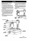
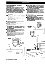
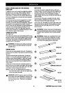
• Stand a framing square on the table with the short
leg pointing up against the saw blade and the long
lag parallel to the fence. Place the square flat
against the blade between two teeth.
• If both the top and bottom of the saw blade are flat
against the square, no adjustment is needed.
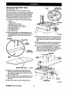
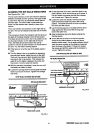
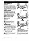
• If the saw blade gaps at the top or bottom, remove
the bevel index cap by removing the two phillips
head screws (below the handle). You will see four
socket head screws.
• Loosen the socket head screws with a 1/4 in. hex
key. Rotate the motor slightlywhile holding the
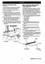
square against the saw blade and table top.
• Slightly tighten each of the four screws and recheck
the blade and framing square.
ARM LOCKKNOB
• if there are no gaps, fullytighten each screw. If
there is still a gap, repeat the previous two steps.
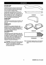
• Check the bevel indicatoron the yoke assembly
near the handle. It should read 0". If it does not,
reset it by loosening the screws and rotating the
bevel index cap. Retighten the two screws.
• Loosen the carriage lock knob.
BLADESQUARETOTABLE
NOADJUSTMENTNEEDED
FRAMING
SQUARE
_ BLADE
TABLE/ Fig. 30 B
FRONTTABLE
INDEXCAP
BEVEL
LOCK
LEVER
GAP - ADJUSTMENTNEEDED Fig. 30 C
BEVELINDEX
CAPREMOVED
ELEVATING SOCKET
HANDWHEEL Fig. 30 A HEADSCREWS LOCK LEVER
Fig. 30 D
CRRFTSMIIII"RADIALSAW315.220380 38