G0504 16" Horizontal Resaw Bandsaw -21-
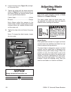
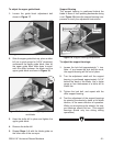
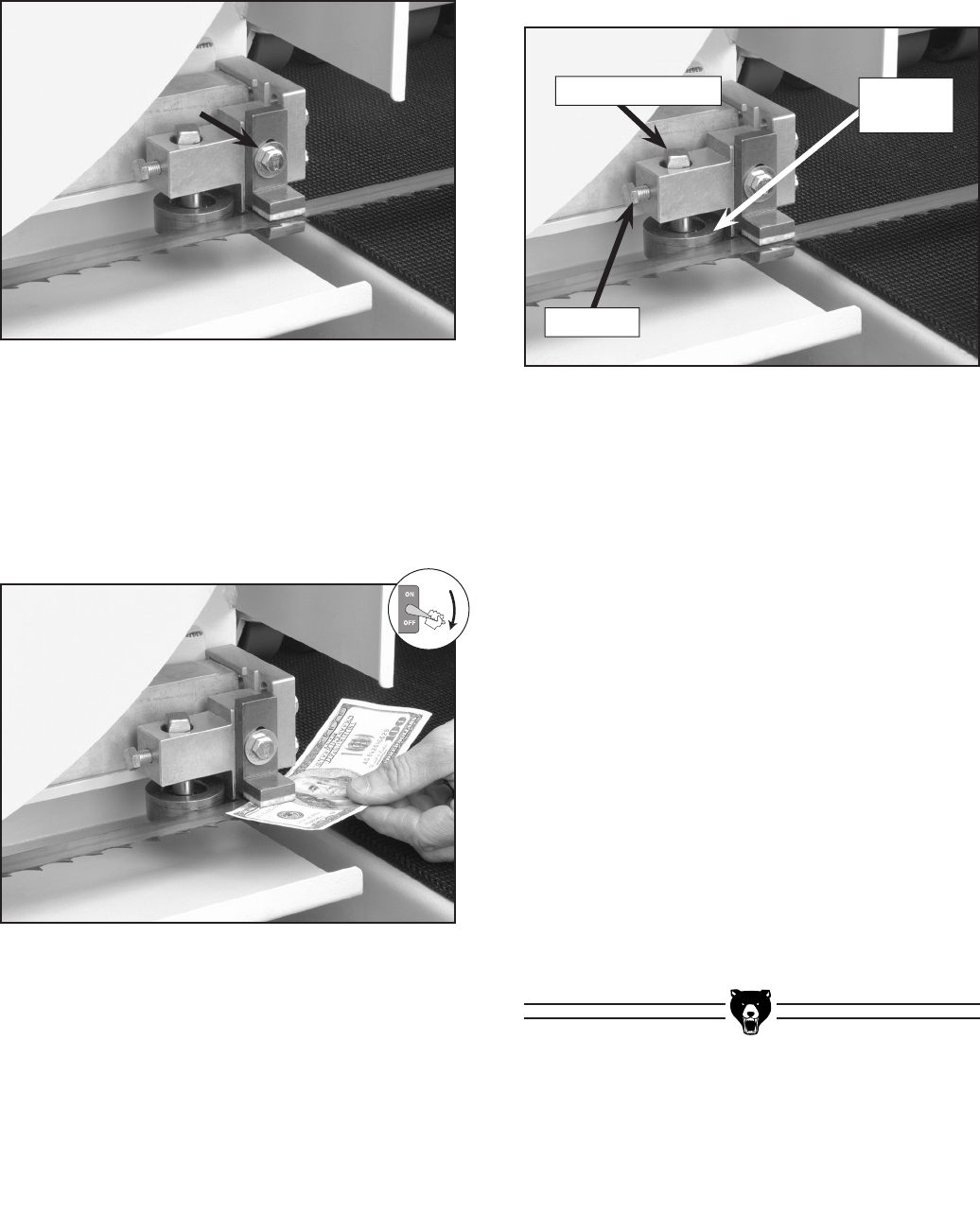
Figure 19. Support bearing components.
To adjust the support bearings:
1. Loosen the lock bolt approximately
1
⁄4 turn.
Note—If you loosen the lock bolt too much,
the support bearing will fall out of place.
2. Turn the adjustment shaft until the support
bearing is positioned approximately 0.016"
behind the back of the blade. Use a feeler
gauge or four thicknesses of a dollar bill to
check this.
3. Tighten the lock bolt, and repeat with the
other support bearing.
4. Test the adjustment of the support bearings
by spinning the wheels by hand, at full blade
tension, in the same direction of operation.
While you are spinning the wheels, the sup
-
port bearings should not turn. (The support
bearings should only turn during cutting
operations.)
Support Bearing
The support bearing is positioned behind the
blade to brace it from pushing backwards during
a cut.
Figure 19 shows the support bearing com-
ponents to clarify the adjustment instructions.
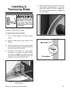
Figure 17. Guide block adjustment bolt.
Figure 18. Dollar bill between upper guide block
and blade.
2. Slide the upper guide block up, place a dollar
bill (as a quick gauge for 0.004" clearance)
underneath the upper guide block, then let
the upper guide block slide down to sand
-
wich the dollar between the blade and the
upper guide block as shown in
Figure 18.
3. Keep the dollar bill in place and tighten the
upper guide block.
4. Remove the dollar bill.
5. Repeat Steps 1-4 with the blade guide on
the other side of the conveyor.
To adjust the upper guide block:
1. Loosen the guide block adjustment bolt
shown in
Figure 17.
Adjustment Shaft
Lock Bolt
Support
Bearing


