


-38- G0504 16" Horizontal Resaw Bandsaw
3. Study the written measurements on your
test piece. Note—DO NOT place too much
importance on the first and last six inches of
the board, because the board will only have
been under one pressure roller during that
part of the cut.
— If the measurements are more than 0.030"
different from one side to the other, you
should adjust the conveyor table.
To adjust the conveyor table:
1. Disconnect the resaw from the power
source!
2. Use your test board to determine which
direction the conveyor table needs to be
moved. For example, if the right side of the
board was thicker than the left side—you
will need to move either the right side of the
conveyor up or move the left side of the con-
veyor down.
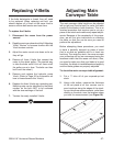
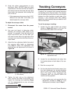
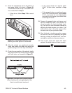
3. Adjust the four adjustment bolts that control
the conveyor table height as determined
from Step 2. Note—For adjustment bolt
locations see the adjustment bolt shown in
Figure 39.
Figure 39. Conveyor table adjustment bolts
(1 of 4 shown).
4. Tighten the lock nuts on the adjustment
bolts, connect the resaw to the power, and
repeat the checking and adjusting
Steps
until the measurements on your cut piece
are within 0.030".
Tracking Conveyors
“Tracking” the conveyor belts means balancing
the way they ride on the end rollers. The convey
-
ors are tracking correctly when they are centered
between the roller brackets on each side of the
conveyor. If the conveyor belts start rubbing
against the roller brackets, then you need to track
them as described.
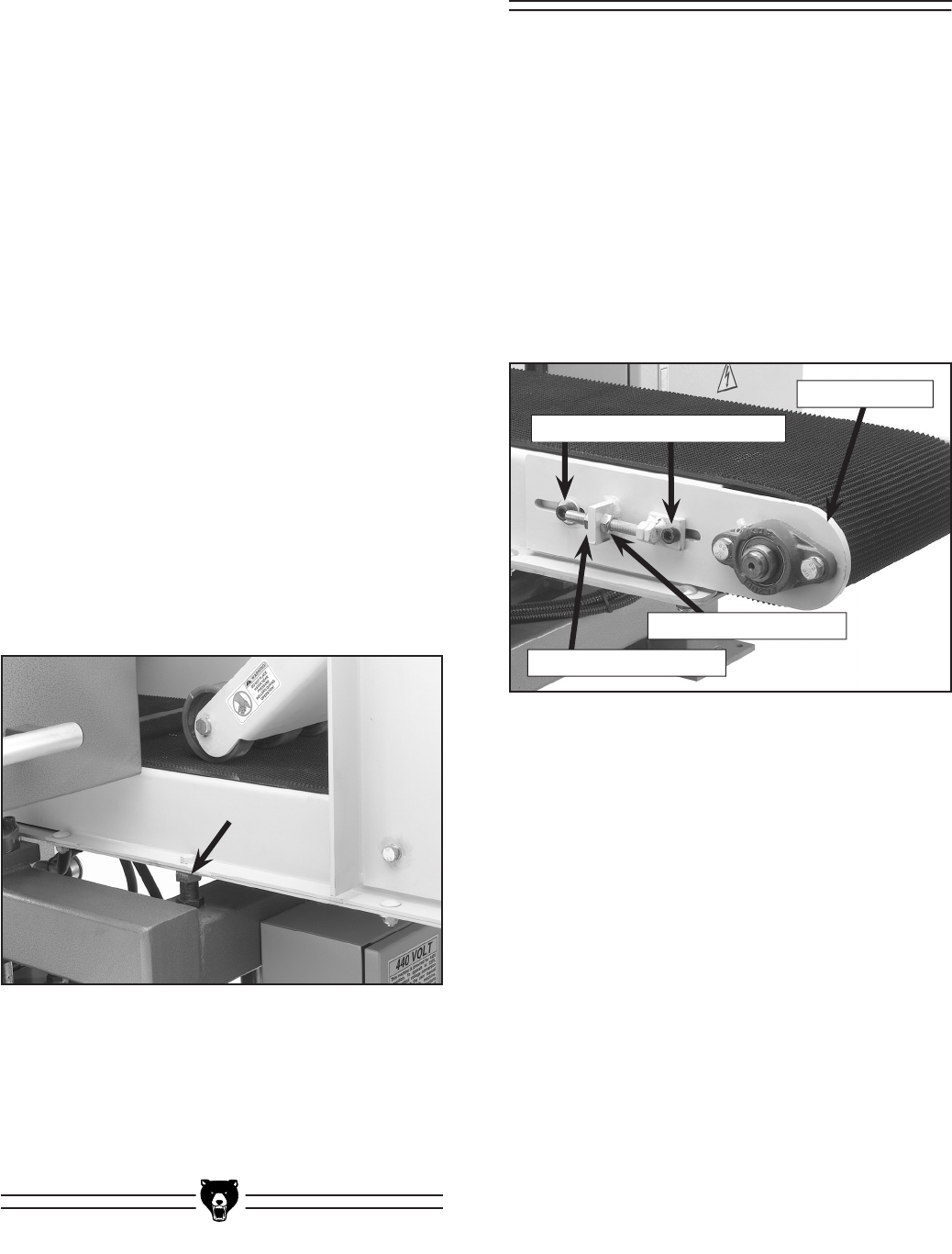
To set the conveyor tracking
:
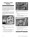
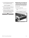
1. Loosen the two roller bracket cap screws
(shown in
Figure 40) about
3
⁄4 of a turn. Do
this on the both sides of the conveyor.
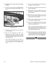
2. Loosen the rear adjustment nuts away from
the bracket plates on both sides of the con
-
veyor.
3. Start the conveyor belt.
4. On the side that the belt tracks toward, turn
the front adjustment nut counter-clockwise
half of a turn, and watch the belt tracking.
Note—The effect of the adjustment can
sometimes take two minutes before the
results are fully apparent.
— If the tracking was not corrected by this
adjustment, proceed to Step 5. If the
tracking was corrected, skip to Step 6
.
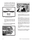
Figure 40. Roller bracket cap screws and
adjustment nuts.
Roller Bracket Cap Screws
Rear Adjustment Nut
Front Adjustment Nut
Roller Bracket