


-42- G0504 16" Horizontal Resaw Bandsaw
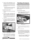
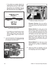
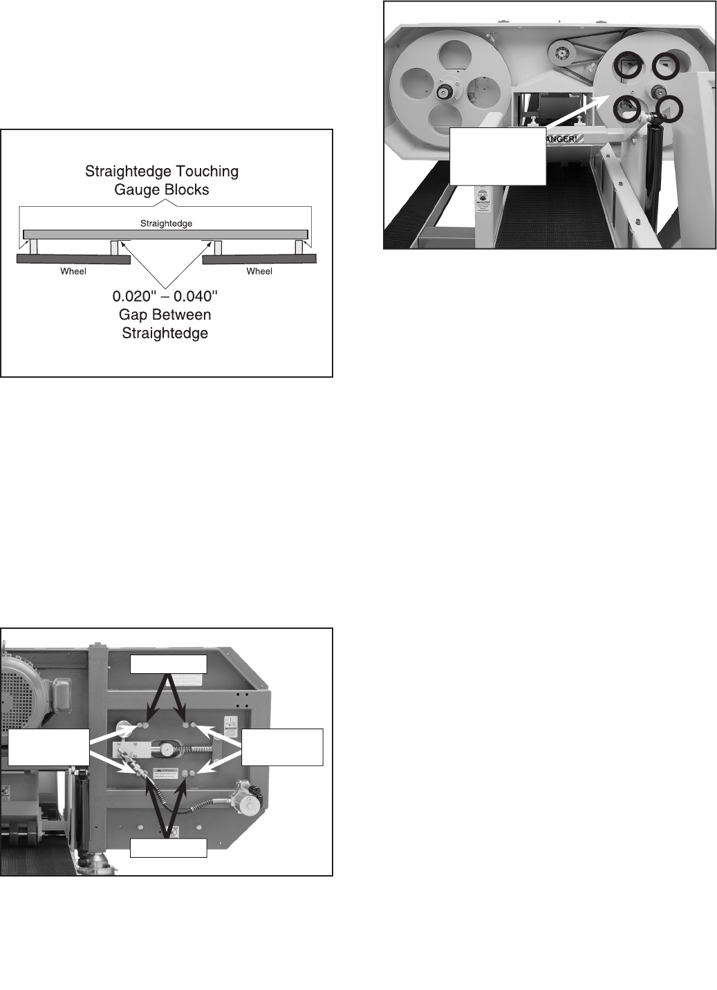
Figure 46. Overhead view of straightedge on
blade wheel gauge blocks.
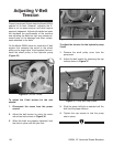
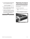
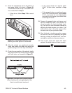
Figure 47. Tension wheel adjustment bolts.
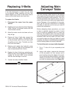
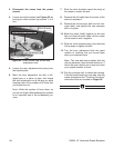
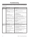
Figure 48. Drive wheel adjustment controls
(fourth bolt hidden in this picture).
— If the wheels are properly aligned, the
straightedge will touch both inside gauge
blocks and there will be a 0.020"–0.040"
gap between the straightedge and the
outside gauge blocks, as shown in
Figure
46. If this is the case, skip to Step 9.
— If the wheels are not positioned as shown
above, determine which direction they
need to move in order to be correct, then
proceed to Step 7 to begin the adjustment
process.
7. Look at the backside of the wheel guard and
learn the controls shown in
Figures 47 & 48
by reading the text that follows.
Adjustment
Screws
Drive Wheel
Adjustment
Bolts
Movement Direction—The bolt position
around the wheel shaft determines the part
of the wheel that will move when that bolt is
turned.
Moving Forward—To move part of the
wheel forward, loosen the appropriate lock
bolts the same amount that you will tight
-
en their neighboring adjustment bolts. (By
“appropriate” we mean the bolts that control
the direction that your wheel needs to be
moved.) In the case of the main drive wheel
adjustments, always loosen the jam nuts
before moving the adjustment bolts, and
always tighten the jam nuts after moving the
adjustment bolts.
Moving Backward—To move part of the
wheel backward, loosen the appropriate
adjustment bolt, then tighten the neighboring
lock bolt.
8. Adjust the wheels as necessary until the
wheel position is correct when checked with
the straightedge and continue to Step 9
.
Adjustment
Screws
Lock Bolts
Lock Bolts