


Model T25920/T25926 (Mfd. Since 08/14)
-15-
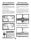
Site Considerations
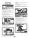
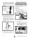
Figure 8. T25920 minimum working clearances.
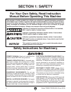
Figure 9. T25926 minimum working clearances.
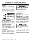
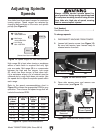
Children and visitors may be
seriously injured if unsuper-
vised around this machine.
Lock entrances to the shop
or disable start switch or
power connection to prevent
unsupervised use.
Workbench Load
Refer to the Machine Data Sheet for the weight
and footprint specifications of your machine.
Some workbenches may require additional rein-
forcement to support the weight of the machine
and workpiece materials.
Consider anticipated workpiece sizes and addi-
tional space needed for auxiliary stands, work
tables, or other machinery when establishing a
location for this machine in the shop. Below is
the minimum amount of space needed for the
machine.
Placement Location
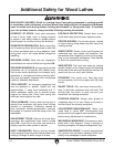
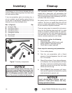
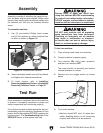
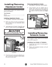
Figure 11. "Direct Mount" setup.
Machine Base
Workbench
Lag Screw
Flat Washer
Another option is a "Direct Mount" (see example
below) where the machine is secured directly to
the workbench with lag screws and washers.
Bench Mounting
The base of this machine has mounting holes
that allow it to be fastened to a workbench or
other mounting surface to prevent it from moving
during operation and causing accidental injury or
damage.
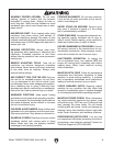
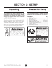
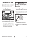
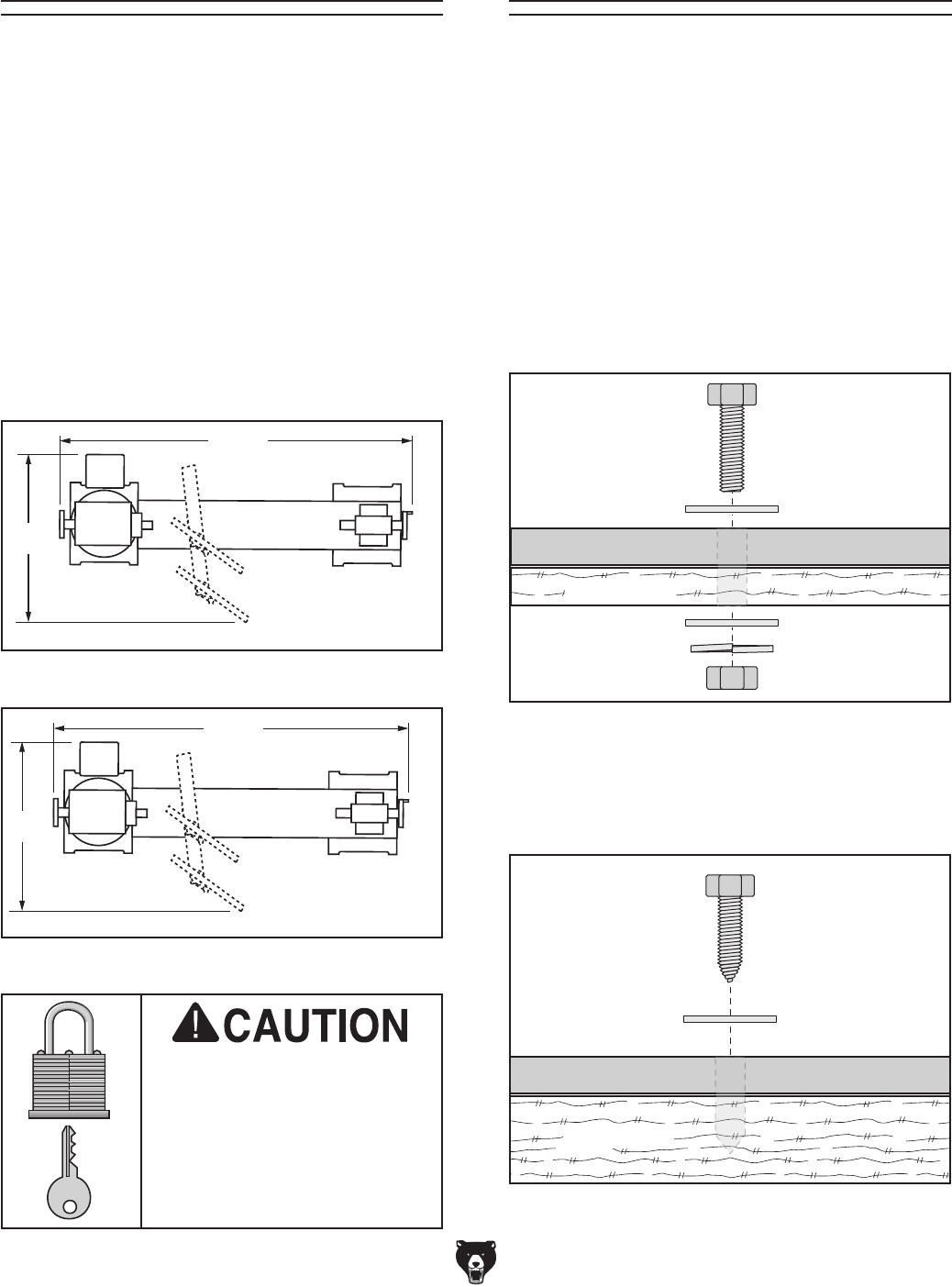
The strongest mounting option is a "Through
Mount" (see example below) where holes are
drilled all the way through the workbench—and
hex bolts, washers, and hex nuts are used to
secure the machine in place. The rubber feet
on the bottom of the base must be removed to
"Through Mount" the lathe.
Machine Base
Workbench
Hex
Bolt
Flat Washer
Flat Washer
Lock Washer
Hex Nut
38
3
⁄4"
17
37
3
⁄4"
17
3
⁄4"
Figure 10. "Through Mount" setup.