


-20-
Model T25920/T25926 (Mfd. Since 08/14)
The tailstock is equipped with a cam-action
clamping system to secure it to the lathe bed.
When the lock lever is engaged, a plate lifts and
secures the tailstock to the bed.
Tool Needed:
Wrench 12mm ................................................... 1
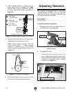
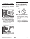
To position tailstock along bed:
1. Disengage lock lever and move tailstock to
desired position (see Figure 20).
Adjusting Tailstock
2. Re-engage lock lever.
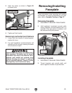
— If lock lever will not lock or unlock, then
adjust tailstock base mounting nut (locat-
ed on underside of tailstock base) in small
increments to achieve proper clamping
pressure (see Figure 21).
Figure 21. Mounting nut location.
Tailstock Mounting Nut
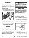
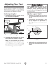
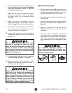
5. Move belt tension lever down to tension belt,
then tighten belt tension lever screw.
Note: When properly tensioned, the belt
should deflect about
1
⁄2" when moderate
pressure is applied to the belt mid-way
between upper and lower pulleys, as shown in
Figure 19.
6. After verifying belt tension is correct, re-install
rear cover and close side access cover.
Pulley
Deflection
Pulley
Figure 19. Checking belt deflection.
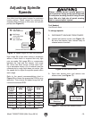
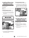
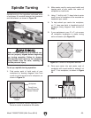
4. Locate desired speed on speed chart on
top of control box (see Figure 15 on Page
19) and move belt to necessary grooves
on motor and spindle pulleys, as shown in
Figure 18.
1
⁄2"
A
B
C
= High Range
1600–3800 RPM
= Mid Range
1250–2800 RPM
= Low Range
650–1450 RPM
A
B
C
Spindle
Motor
(Viewed from Back of Headstock)
Figure 18. Speed ranges for each belt position.
Figure 20. Typical tailstock lock lever to adjust
tailstock position.
Lathe Bed
Lock Lever