


Model T25920/T25926 (Mfd. Since 08/14)
-21-
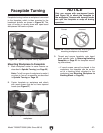
The tool rest base is equipped with a cam-action
clamping system to secure it to the lathe bed.
When the lever is engaged, a locking plate lifts up
and secures the tool rest base to the bed.
Positioning Along Bed
1. Disengage base lock lever and slide tool rest
base along bed (see Figure 22).
Adjusting Tool Rest
2. Re-engage the tool rest base lock lever to
secure the tool rest assembly in position.
Note: The large clamping hex nut under-
neath the tool rest base will require occa-
sional adjusting to ensure proper clamping
pressure of the tool rest assembly to the bed.
Turn this hex nut in small increments to fine
tune the clamping pressure as needed.
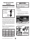
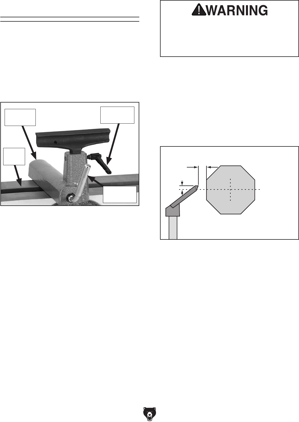
Figure 22. Typical tool rest controls to adjust
position and height.
Tool Rest
Lock Lever
Tool Rest
Base
Lathe
Bed
Base Lock
Lever
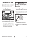
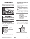
Adjusting Angle or Height
1. Loosen the tool rest base lock lever and the
tool rest lock lever to adjust the position of the
tool rest.
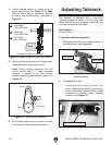
2. Position the tool rest approximately
1
⁄4" away
from the workpiece and approximately
1
⁄8"
above the workpiece center line, as shown in
Figure 23.
3. Re-tighten the tool rest lock lever and the tool
rest base lock lever to secure the tool rest in
position.
Workpiece
Center Line
Distances
Tool Rest
1
⁄8"
1
⁄4"
Figure 23. Tool rest position relative to
workpiece.
Always operate the lathe with the tool
rest assembly firmly locked in position.
Otherwise, serious personal injury may
occur by the tool being pulled from the
operator's hands.