


-10-
Model T27313 (Mfd. Since 01/15)
Assembly
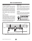
The support arms must be oriented in a specific
way depending on which lathe the copy attach-
ment will be mounted. Figure 5 shows the sup-
port arm orientation for each of the four wood
lathes onto which the model T27313 mounts. The
arms will be mounted on top of the lathe bed with
the mounting holes extending approximately 6"
past it.
All assembly and adjustment instructions
assume that your lathe is axially aligned,
i.e., headstock and tailstock are centered on
the same axis. Consult your lathe owner’s
manual for proper procedure.
Selecting correct support arm orientation
is critical to ensure that cutting tool will be
positioned at spindle centerline.
1. DISCONNECT MACHINE FROM POWER!
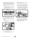
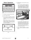
2. Mount (2) support arms perpendicular to,
and on top of, lathe bed with (2) support arm
clamping plates, (2) support arm clamps, (2)
M8-1.25 x 150 carriage bolts, (2) 8mm fender
washers, and (2) M8-1.25 knobs. Carriage
bolt head should be on top of support arm
clamp, and support arm clamping plates
should be below lathe bed (see Figure 6).
Note: Leave knobs finger tight so support
arm assembly can slide across lathe bed.
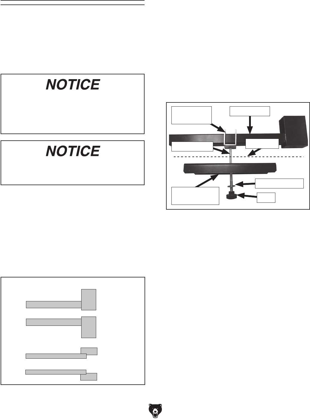
Figure 6. Example of support arm assembly
setup for G0733 wood lathe.
Knob
Fender Washer
Carriage Bolt
Support Arm
Support Arm
Clamp
Support Arm
Clamping Plate
Mounting Support Arms
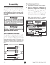
Selecting Support Arm Setup
G0733
G0584
G0462
G5979
Figure 5. Support arm orientation and matching
lathe.
(Rear
of
Bed)
(Front
of
Bed)
(Viewed from Headstock)
The assembly process consists of selecting the
appropriate support arm orientation, mounting
the support arms and copy attachment bed, and
finally aligning the copy attachment. The align-
ment procedures are critical to the proper opera-
tion of the copy attachment, DO NOT skip these
procedures.
Lathe Bed