


Model T27313 (Mfd. Since 01/15)
-11-
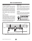
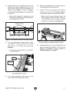
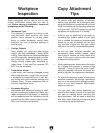
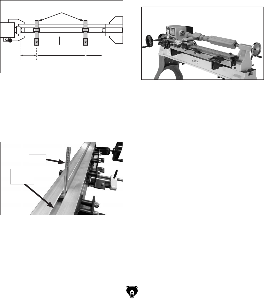
3. Adjust support arm assemblies so they are
centered on points measuring 20% of dis-
tance across lathe bed from headstock to
tailstock (see Figure 7). Front of support
arms should extend beyond front of lathe bed
by about 6".
— Some minor degree of variation may be
necessary to eliminate any interference to
normal operation of lathe.
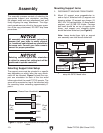
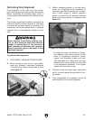
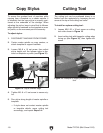
4. Tip copy attachment upside down so bot-
tom channel is facing upwards, then slide
(2) M10-1.5 x 100 T-bolts into channel (see
Figure 8).
— If using short support arms, use (2) M10-
1.5 x 45 T-bolts.
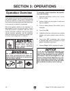
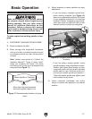
6. Mount copy attachment so tool will reach cor-
rect starting point for desired cut.
7. Install (2) 10mm flat washers and (2) M10-
1.5 hex nuts onto T-bolts installed in Step 4.
Then tighten support arm assembly knobs.
— Make certain copy attachment does not
block access to lathe controls. Some lat-
eral adjustment can be made to assure
clearance if necessary (see Figure 9).
Figure 8. T-bolt installed into slot on bottom of
copy attachment (1 of 2).
T-Bolt
T-Bolt
Channel
5. Turn copy attachment right side up, then
insert T-bolts into support arm holes.
Figure 9. Example of copy attachment mounted
on lathe without obstructing lathe controls.
8. Congratulations, your copy attachment has
been successfully installed. It must now be
aligned for parallelism. Please proceed to
Rough Alignment on Page 12.
Figure 7. Attachment locations for support arms.
6"
20%
60%
20%
Support Arms