


-12-
Model T27313 (Mfd. Since 01/15)
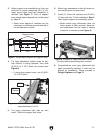
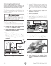
5. Loosen (2) knobs securing support arm
assemblies, then slide copy attachment bed
over boards until leading edge is even with
marks on both left and right sides (see Figure
10).
6. Tighten (2) knobs securing support arm
assemblies to lathe bed.
7. Remove gauge boards.
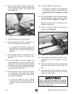
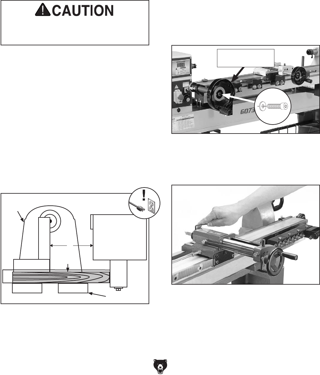
8. Install longitudinal-feed handwheel with (1)
M6-1 x 12 cap screw and (1) 6mm flat washer
(see Figure 11).
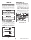
To perform rough alignment:
1. DISCONNECT MACHINE FROM POWER!
2. Prepare two gauge boards approximately
1
1
⁄8" thick, 6–8'' wide and 2–3'' long.
3. Clamp gauge boards onto lathe bed, one at
headstock and other at tailstock.
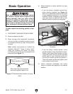
4. Place a machinist’s square centered on
tailstock on top of gauge board and measure
3'' toward copy attachment bed (see Figure
10). Place a precise mark across width of
wood. Repeat with gauge board located at
headstock.
Performing Rough Alignment
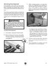
Use caution when handling copy attach-
ment cutting tool. Its sharp edges could
cause cuts if handled improperly.
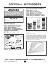
Figure 12. Securing cutting tool.
10. Rough alignment is now complete. Please
proceed to Performing Final Alignment on
Page 13.
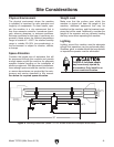
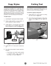
Once the copy attachment bed is attached to the
support arms, the entire assembly must be adjust-
ed parallel with the lathe to function correctly.
The following procedures provide details on the
process of adjusting the copy attachment to
achieve parallelism.
9. Install cutting tool into arbor and tighten pre-
installed collar set screw (see Figure 12).
Figure 11. Longitudinal-feed handwheel installed
on copy attachment.
Longitudinal-Feed
Handwheel
Figure 10. Use of gauge boards for alignment.
Copy
Attachment
Bed
(View from Headstock)
Gauge
Board
Lathe Bed
Tailstock
3"