


SKU 95668 For technical questions, please call 1-800-444-3353 PAGE 10
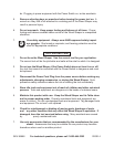
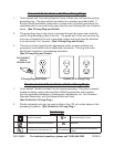
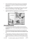
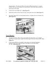
5. Place the Wood Shaper’s Work Table (52) upside down on two sturdy blocks
that are at least 3-1/2” off the oor. Make sure the Spindle (105) DOES NOT
touch the oor or the weight of the Wood Shaper may damage the Spindle.
(See Figure G.)
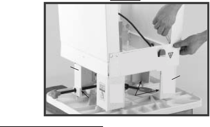
6. Place the Stand assembly on the Wood Shaper and attach it with the Carriage
Bolts (9), 3/8” Flat Washers (10), and Hex Nuts (11). Then have an assistant
help you turn the Wood Shaper unit upright. (See Figure G.)
7. Level the Wood Shaper with a carpenter’s level. If necessary, move the Stand
slightly until it is level. Then, tighten all Bolts and Nuts on the Stand.
FIGURE G
STAND ASSEMBLY
WORK TABLE
(52)
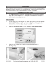
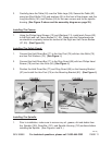
Optional Table Spacer Installation:
Your shaper comes with a Table Spacer Installation Kit that will enable you 1.
to make shallow cuts and utilize the upper blade area of most router bits with
shanderd-length shanks. This is an optional feature that is not required for most
applications.
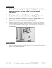
Unplug the shaper power cord. Remove the four table corner Hex Bolts (66), 2.
then remove the three Spindle Housing Hex Bolts (95). Lift the Table (52) off of
the stand assembly. (See Figure G above and the assembly diagram on page
29.)
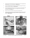
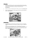
Locate the package, (included with your shaper), that contains all the hardware 3.
for installing the spacers. There should be ve M12 Long Bolts (151), two M12
Short Bolts (152) and seven 1/2” Spacers (150). Position one spacer over each
of the four corner bolt holes and one over each of the three spindle housing bolt
holes.
(66)
(66)
(28)
(28)
(28)
REV 07j