


CHAPTER 2
Setup and Configuration
10 StudioPix™ Pixelation Luminaire User Manual
Linking StudioPix Fixtures
StudioPix™ fixtures operate on a standard DMX512 link controlled by a DMX console. The
number of fixtures on a link will be determined by the combined number of channels required by
all the fixtures. A StudioPix fixture using Standard protocol requires 70 channels on a DMX512
link. Attach the fixture to the link using data-grade cable and 5-pin XLR cable connectors.
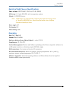
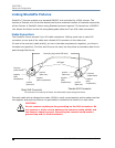
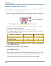
Cable Connectors
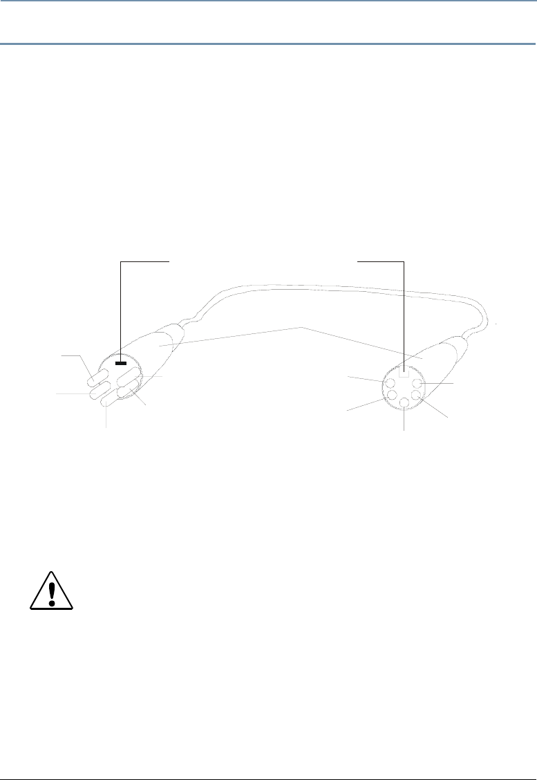
The StudioPix fixture accepts 5-pin XLR cable connectors. Cabling must have a male XLR
connector on one end of the cable and a female XLR connector on the other end.
Pin one is the common (cable shield), pin two is the data complement (negative), pin three is
the data true (positive). Pins four and five are not used, but they allow a secondary data link to
pass through the fixture.
Test each cable with a voltage/ohm meter (VOM) to verify correct polarity and to make sure that
the negative and positive pins are not grounded or shorted to the shield or to each other.
CAUTION!
Do not connect anything to the ground lug on the XLR connectors. Do
not connect or allow contact between the common (cable shield) and
the fixture’s chassis ground. Grounding the common could cause a
ground loop and/or erratic behavior.
positive
(data true)*
negative
(data
complement)*
Common
(cable shield)
2
1
3
Male XLR Connector
Female XLR Connector
positive
(data true)
negative
(data
complement)
XLR shell
Common
(cable shield)
1
2
3
4
5
5
4
positive
(data true)*
negative
(data complement)*
negative
(data
complement)
positive
(data true)
*This data line is not used b
y
the fixture
,
but allows data to
p
ass throu
g
h the fixture.
Grounding lug (inside XLR shell)