


CHAPTER 2
Setup and Configuration
StudioPix™ Pixelation Luminaire User Manual 11
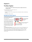
Connecting to the Link
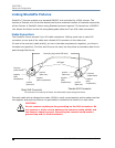
To link one or more fixtures to a DMX controller:
1. Connect the male XLR connector of a DMX Data cable to the controller’s DMX Data Out
connector.
2. Connect the Data cable’s female XLR connector to the Data In connector of the first (or
next) fixture on the DMX link.
3. Continue linking the remaining fixtures connecting a cable from the Data Out connector of
each fixture to the Data In connector of the next fixture on the link.
4. Terminate the link by
installing a 120 ohm,
1/4 watt (minimum)
terminator in the
fixture’s
Data Out
(female) cable
connector in the last
fixture on each DMX link. A terminator on the last fixture of the link prevents data
reflection, which can corrupt the data communication on the link.
Powering On the Fixture
To power on the StudioPix fixture, simply connect it to a 100-230 V AC power source.
Once the StudioPix fixture is connected to a power source, it automatically begins a homing
procedure to verify the major functions of the fixture.
WARNING:
This equipment is designed for connection to a branch circuit
having a maximum overload protection of 20 A.
CAUTION:
Do not power on the fixture until verifying that the line cord
cap is suitable for the power source in your location. For more
information, see
Installing a Power Cord Cap on page 7.
1
2
0
1
2
3
4
5
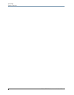
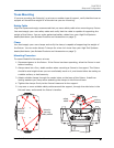
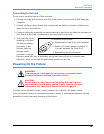
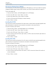
To construct a terminator:
1. Disassemble a male 5-pin XLR connector.
2. Solder a 120 ohm resistor, minimum of
1/4 watt, between Pin 2 and Pin 3.
3. Reassemble the XLR connector.