


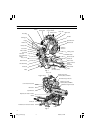

10
9. Installing the holders ... (Optional accessory)
The holders help keep longer workpieces stable and
in place during the cutting operation.
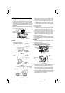
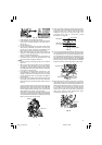
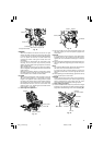
(1) As indicated in Fig. 14, use a steel square for aligning
the upper edge of the holders with the base surface.
Loosen the 6 mm wing nut. Turn a height adjustment
bolt 6 mm, and adjust the height of the holder.
(2) After adjustment, firmly tighten the 6 mm wing nut
and fasten the holder with the 6 mm knob bolt
(optional accessory). If the length of Height
Adjustment Bolt 6 mm is insufficient, spread a thin
plate beneath. Make sure the end of Height
Adjustment Bolt 6 mm does not protrude from the
holder.
Fig. 14
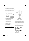
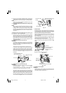
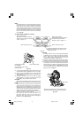
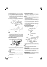
10. Stopper for precision cutting ... (Stopper and holder
are optional accessory)
The stopper facilitates continuous precision cutting
in lengths of 285 mm to 450 mm.
To install the stopper, attach it to the holder with the 6
mm knob bolt as shown in Fig. 15.
Fig. 15
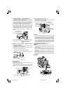
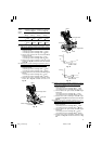
11. Using an ink line
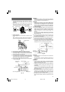
(1) Right angle cutting
Loosen the 6 mm knob bolt and contact the tip of the
guard with the workpiece.
Aligning the ink line on the workpiece with the groove
of the guard, the workpiece is cut on the ink line (Fig.
16).
Fig. 16
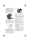
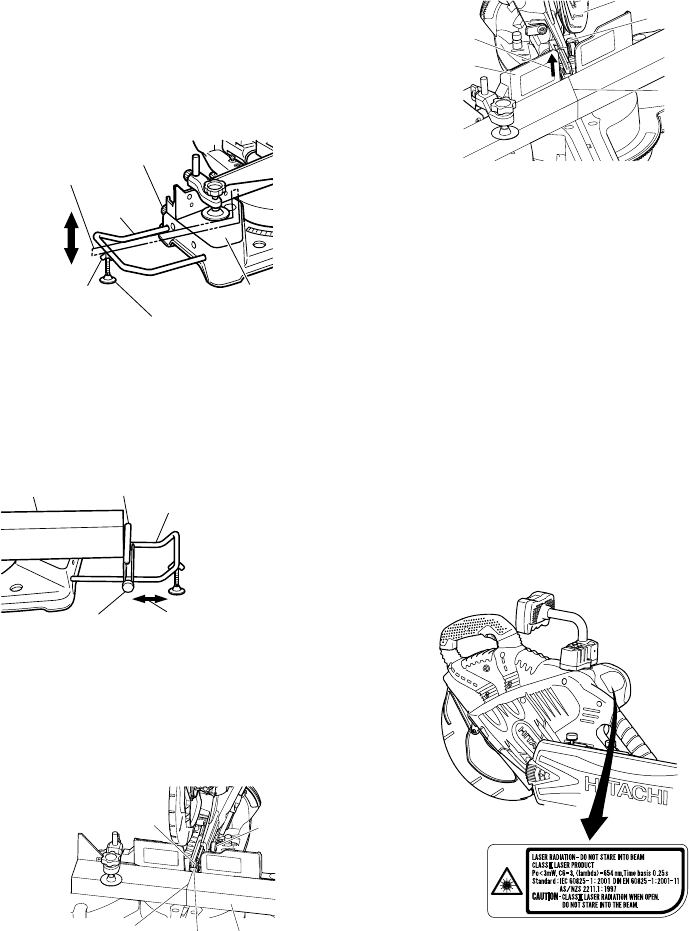
(2) Miter cutting and compound cutting
(Miter cutting + bevel cutting)
Upon lowering the motor section, the lower guard is
raised and the saw blade appears.
Align the ink line with the saw blade (Fig. 17).
Fig. 17
CAUTION
In some arrangements when the turntable is rotated,
the guard projects from the fence surface. Loosen the
6 mm knob bolt and push the guard to the retracted
position. Never lift the lower guard while the saw
blade is rotating. When cutting at an angle to the right
or more, please slide the guard to the rear. The guard
and sub-fence (A) and sub-fence (B) will not only make
contact and adversely affect cutting accuracy, this
could also result in damage to the guard.
12. Position adjustment of laser line
WARNING
* Make sure before plugging the power plug into the
receptacle that the main body and the laser marker
are turned off.
* Exercise utmost caution in handling a switch trigger
for the position adjustment of the laser line, as the
power plug is plugged into the receptacle during
operation.
If the switch trigger is pulled inadvertently, the saw
blade can rotate and result in unexpected accidents.
* Do not remove the laser marker to be used for other
purposes.
CAUTION
Fig. 18
6 mm knob bolt
(Optional accessory)
Holder
(Optional
accessory)
Steel square
Base surface
6 mm wing nut
(Optional accessory)
Height adjustment bolt 6 mm
(Optional accessory)
Workpiece
Stopper (Optional accessory)
Holder (Optional accessory)
6 mm knob bolt
(Optional accessory)
Move
Marking (pre-marked)
Workpiece
Guard
Saw blade groove
6 mm knob
bolt
6 mm knob
bolt
Lower guard
Move the
guard
backward
Sub fence (B)
Marking
(pre-marked)
03Eng_C12LSH_Eng 4/26/07, 5:32 PM10