


16
(2) Re-tighten the side handle to secure the turntable in
the desired position.
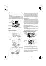
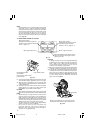
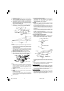
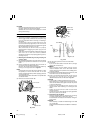
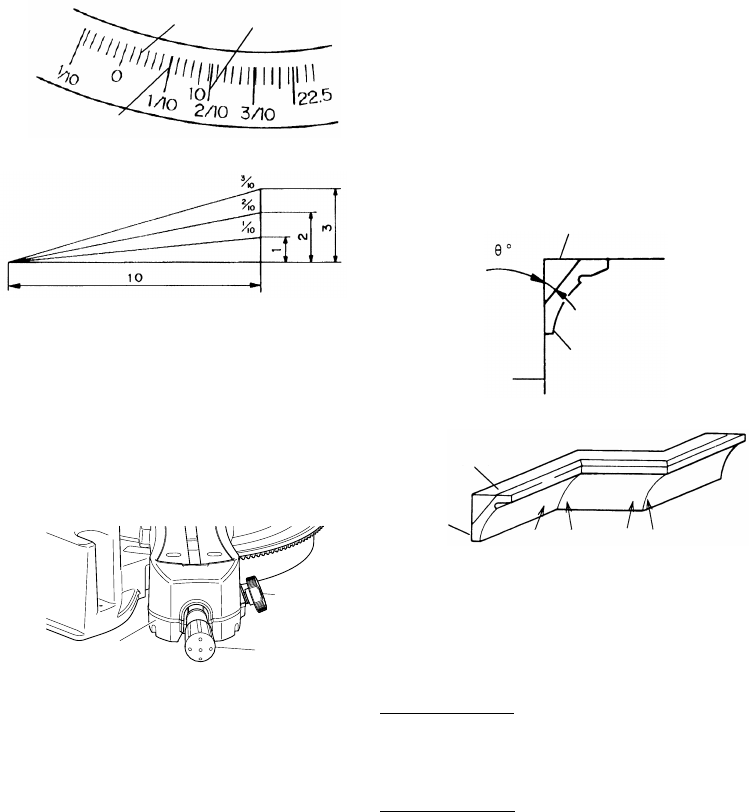
(3) The miter scale (Fig. 37) indicates both the cutting angle
on the angle scale and the gradient on the grade scale.
(4) The gradient, which is the ratio of the height to the
base of the triangular section to be removed, may be
used for setting the miter scale instead of the cutting
angle, if desired (see Fig. 37).
(5) Therefore, to cut a workpiece at a grade of 2/10, set
the indicator to position a as indicated in Fig. 37.
Fig. 37
Fig. 38
NOTE
* Positive stops are provided at the right and left of the
0° center setting, at 15°, 22.5°, 31.6° and 45° settings.
Check that the miter scale and the tip of the indicator
are properly aligned.
* Operation of the saw with the miter scale and indicator
out of alignment, or with the side handle not properly
tightened, will result in poor cutting precision.
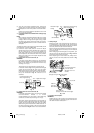
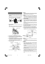
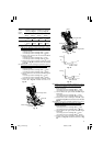
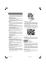
10. Miter angle fine adjustment
(1) Rotate the turntable to the miter angle you need.
(2) When making fine adjustments of the miter angle, turn
the knob (A) while pulling up the lever (Fig. 39).
Fig. 39
NOTE
Turning knob (A) clockwise, allows fine adjustment
of the turntable to the right. Turning knob (A)
counterclockwise, allows fine adjustment of the
turntable to the left.
(3) After adjusting to the desired angle, tighten the side
handle.
CAUTION
Always check that the side handle is secured and the
turntable is clamped.
If you attempt angle cutting without clamping the
turntable, then the turntable might shift unexpectedly
causing injuries.
Angle scale
Grade scale
a
Miter scale
11. Compound cutting procedures
Compound cutting can be performed by following the
instructions in 7 and 10 above. For maximum
dimensions for compound cutting, refer to
“SPECIFICATIONS” table on page 5.
CAUTION
Always secure the workpiece with the right or left hand
and cut it by sliding the round portion of the saw
backwards with the left hand.
It is very dangerous to rotate the turntable to the left
during compound cutting because the saw blade may
come into contact with the hand that is securing the
workpiece.
In case of compound cutting (angle + bevel) by left
bevel, turn the sub-fence (B) counterclockwise, and
engage in the cutting operation.
In case of compound cutting (angle + bevel) by right
bevel, turn the sub-fence (A) clockwise, and engage
in the cutting operation.
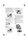
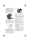
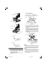
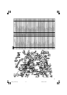
12. Crown molding cutting procedures
Fig. 40 shows two common crown molding types
having angles of (q) 38° and 45°.
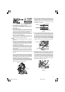
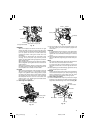
For the typical crown molding fittings, see Fig. 41.
Fig. 40
Fig. 41
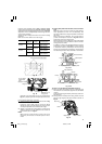
The table below shows the miter angle and the bevel
angle settings that are ideal for the two crown molding
types.
NOTE
For convenience, positive stops are provided for the
miter setting (left and right 31.6°) positions.
For miter cut setting
If the turntable has been set to either of the angles
described, move the turntable adjusting side handle
a little to the right and left to stabilize the position
and to properly align the miter angle scale and the tip
of the indicator before the operation starts.
For bevel cut setting
Turn the clamp lever on bevel section to the left and
check that the position is stable and that the bevel
angle scale and the tip of the indicator are properly
aligned. Then tighten the clamp lever.
Wall
A Upper surface ceiling
B Lower surface
Turntable
Side handle
Knob (A)
Ceiling
Wall
1
2
34
Inside corner Outside corner
03Eng_C12LSH_Eng 4/26/07, 5:32 PM16