


19
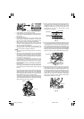
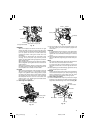
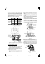
Position crown molding with its WALL CONTACT EDGE
against the guide fence and its CEILING CONTACT EDGE
against the crown molding Stoppers as shown in Fig. 50-b.
Adjust the crown molding Stoppers according to the size
of the crown molding.
Tighten the 6mm wing bolt to secure the crown molding
Stoppers.
Refer to the lower table for the miter angle.
Position Miter
Finished piece
in Fig. 41 angle
For inside
1
Right 45°
Save the right
corner side of blade
2
Save the left
Left 45°
side of blade
For outside
3
Save the right
corner side of blade
4
Right 45°
Save the left
side of blade
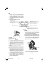
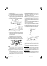
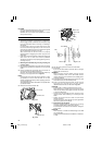
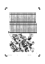
13. Groove cutting procedures
Fig. 51
Fig. 52
Grooves in the workpiece can be cut as indicated in
Fig. 51 by adjusting the 6 mm depth adjustment bolt.
Cutting depth adjustment procedure:
(1) Turn the stopper holder on the direction shown in Fig.
52.
Lower the motor head, and turn the 6 mm depth
adjustment bolt by hand. (Where the head of the 6
mm depth adjustment bolt contacts the hinge.)
(2) Adjust to the desired cutting depth by setting the
distance between the saw blade and the surface of
the turntable (see b in Fig. 51).
NOTE
When cutting a single groove at either end of the
workpiece, remove the unneeded portion with a
chisel.
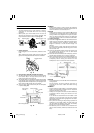
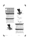
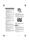
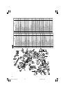
14. Cutting easily-deformed materials, such as aluminum
sash
Materials such as aluminum sash can easily deform
when tightened too much in a vise assembly. This
will cause inefficient cutting and possible overload of
the motor.
When cutting such materials, use a wood plate to
protect the workpiece as shown in Fig. 53-a. Set the
wood plate near the cutting section.
When cutting aluminum materials, coat the saw blade
with cutting oil (non-combustible) to achieve smooth
cutting and a fine finish.
In addition, in case of a U-shaped workpiece, use the
wood plate as shown in Fig. 53-b to ensure stability
in the lateral direction, and clamp it near the cutting
section of the workpiece and tighten it using both the
vise assembly and the clamp available in the market.
Fig. 53-a
Fig. 53-b
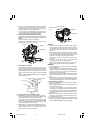
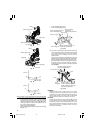
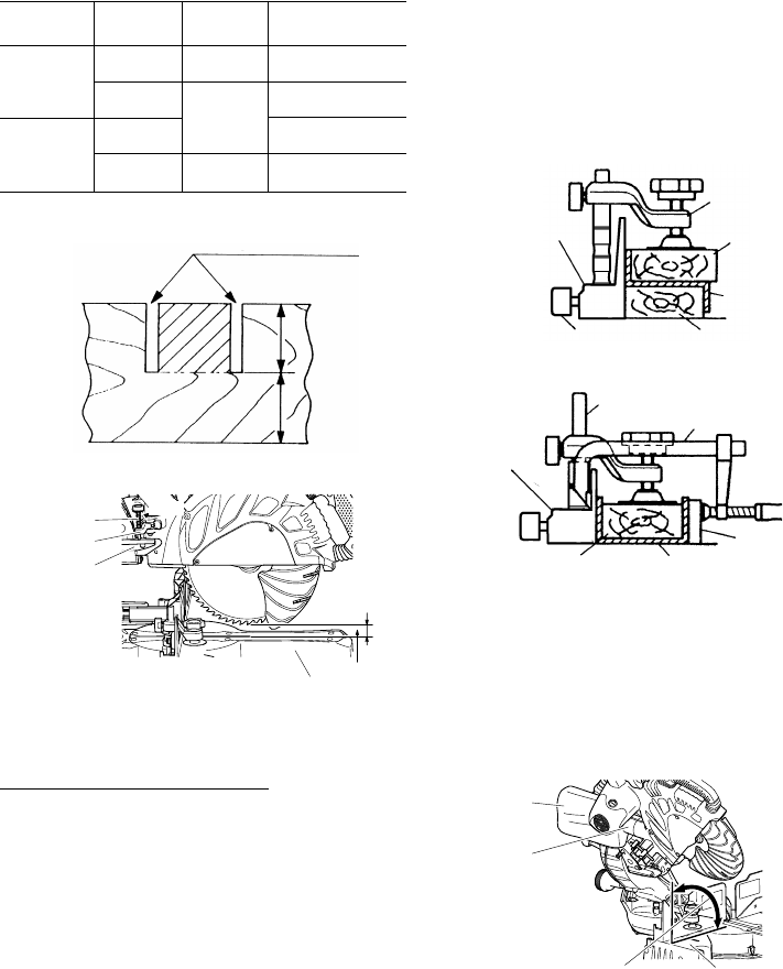
15. How to use the dust bag (Standard accessory)
(1) When the dust bag has become full of sawdust, dust
will be blown out of the dust bag when the saw blade
rotates.
Check the dust bag periodically and empty it before it
becomes full.
(2) During bevel and compound cutting, attach the dust
bag at a right angle to the base surface as shown in
Fig. 54.
Fig. 54
Cut grooves with saw blade
a
b
6 mm depth
adjustment
bolt
Stopper holder
Bottom line of
the groove
Turntable
b
Hinge
Turn
Fence
Vise assembly
Wood plate
Wood plate
Aluminum
sash
6 mm wing bolt (A)
Fence
Wood plate
Vise assembly
Wood plate
Clamp
Dust bag
Duct
Right angle
Base surface
Aluminum sash
03Eng_C12LSH_Eng 4/26/07, 5:32 PM19