


17
To process crown To process crown
Type of
molding at positions molding at positions
Crown
1 and 4 in Fig. 41. 2 and 3 in Fig. 41.
Molding
Miter Angle Bevel Angle Miter Angle Bevel Angle
Setting Setting Setting Setting
45° Type right 35.3°left 30° left 35.3° left 30°
( mark) ( mark) ( mark) ( mark)
38° Type right 31.6°left 33.9° left 31.6° left 33.9°
( mark) ( mark) ( mark) ( mark)
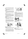
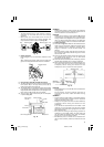
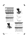
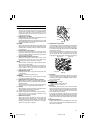
(1) Setting to cut crown moldings at positions 1 and 4
in Fig. 41 (see Fig. 42; tilt the motor head to the left):
1 Turn the turntable to the right and set the Miter
Angle as follows:
* For 45° type crown moldings: 35.3° (
mark)
* For 38° type crown moldings: 31.6° ( mark)
2 Tilt the motor head to the left and set the Bevel
Angle as follows:
* For 45° type crown moldings: 30° (
mark)
* For 38° type crown moldings: 33.9° (
mark)
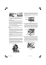
3 Position the crown molding so that the upper
surface (A in Fig. 40) contacts the fence as indicated
in Fig. 44.
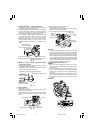
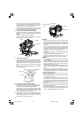
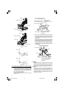
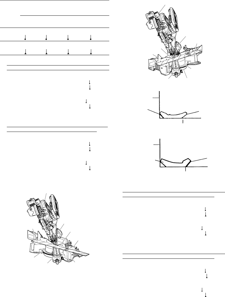
(2) Setting to cut crown moldings at positions 2and 3
in Fig. 41 (see Fig. 43; tilt the head to the left):
1 Turn the turntable to the left and set the Miter
Angle as follows:
* For 45° type crown moldings: 35.3° (
mark)
* For 38° type crown moldings: 31.6° (
mark)
2 Tilt the head to the left and set the Bevel Angle as
follows:
* For 45° type crown moldings: 30° ( mark)
* For 38° type crown moldings: 33.9° (
mark)
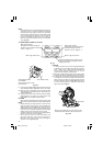
3 Position the crown molding so that the lower
surface (B in Fig. 40) contacts the fence as in
Fig. 45.
Fig. 42
Fig. 43
Fig. 44
Fig. 45
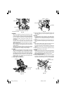
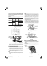
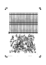
(3) Setting to cut crown moldings at positions 1 and 4
in Fig. 41 (see Fig. 46; tilt the head to the right):
1 Turn the turntable to the right and set the Miter
Angle as follows:
* For 45° type crown moldings: 35.3° (
mark)
* For 38° type crown moldings: 31.6° ( mark)
2 Tilt the head to the right and set the Bevel Angle
as follows:
* For 45° type crown moldings: 30° (
mark)
* For 38° type crown moldings: 33.9° (
mark)
3 Position the crown molding so that the upper
surface (B in Fig. 40) contacts the fence as indicated
Fig. 48.
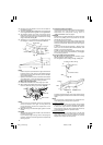
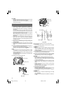
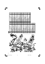
(4) Setting to cut crown moldings at positions 2 and 4
in Fig. 41 (see Fig. 47; tilt the head to the right):
1 Turn the turntable to the left and set the Miter
Angle as follows:
* For 45° type crown moldings: 35.3° (
mark)
* For 38° type crown moldings: 31.6° (
mark)
2 Tilt the head to the right and set the Bevel Angle
as follows:
* For 45° type crown moldings: 30° (
mark)
* For 38° type crown moldings: 33.9° ( mark)
3 Position the crown molding so that the lower
surface (A in Fig. 40) contacts the fence as in Fig.
49.
Bevel angle scale
Fence (A)
Miter angle scale
Turntable
Head
Base
1
4
Bevel angle scale
Base
Miter angle scale
Turntable
Head
Fence (B)
2
3
Fence
A
B
Table on base
Fence
B
A
Table on base
03Eng_C12LSH_Eng 4/26/07, 5:32 PM17