


15
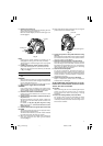
Fig. 33
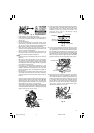
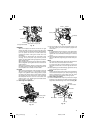
WARNING
When the workpiece is secured on the left or right
side of the blade, the short cut-off portion will come
to rest on the right or left side of the saw blade. Always
turn the power off and let the saw blade stop
completely before raising the handle from the
workpiece.
If the handle is raised while the saw blade is still
rotating, the cut-off piece may become jammed
against the saw blade causing fragments to scatter
about dangerously.
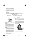
When stopping the bevel cutting operation halfway,
start cutting after pulling back the motor head to the
initial position.
Starting from halfway, without pulling back, causes
the lower guard to be caught in the cutting groove of
the workpiece and to contact the saw blade.
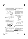
CAUTION
When cutting a workpiece of 75 mm height in the left
45° bevel cutting position or a workpiece of 50 mm
height in the right 45° bevel cutting position, adjust
the lower limit position of the motor head so that the
gap between the lower edge of the motor head and
the workpiece will be 2 to 3 mm at the lower limit
position (refer to “3. Checking the saw blade lower
limit position” on page 8).
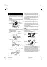
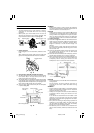
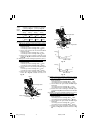
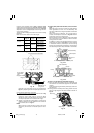
8. Bevel angle fine adjustment
Fig. 34
Set pin (A)
Clamp Lever
Bevel scale
Holder (A)
Indicator
(for right bevel scale)
Pull
Handle
Knob (B)
8 mm bolt (B)
Clamp lever
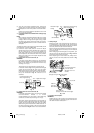
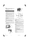
Fig. 35
(1) Grip the handle on the motor head and position it at
the bevel angle you need. Temporarily tighten the
clamp lever.
CAUTION
If not tightened firmly enough the motor head might
suddenly move or slip, causing injuries. Be sure to
tighten the motor head section enough so it will not
move.
(2) When making fine adjustments of the bevel angle, turn
the knob (B) while supporting the handle with your
hand.
NOTE
Turning knob (B) clockwise, allows fine adjustment of
the main unit to the left (as seen from front).
Turning knob (B) counterclockwise, allows fine
adjustment of the main unit to the right (as seen from
front).
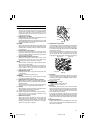
(3) After adjusting to the desired angle, tighten the clamp
lever and clamp the motor head.
CAUTION
Always check that the clamp lever is secured and the
motor head is clamped. If you attempt angle cutting
without clamping the motor head, then the motor
head might shift unexpectedly causing injuries.
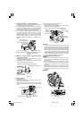
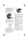
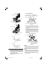
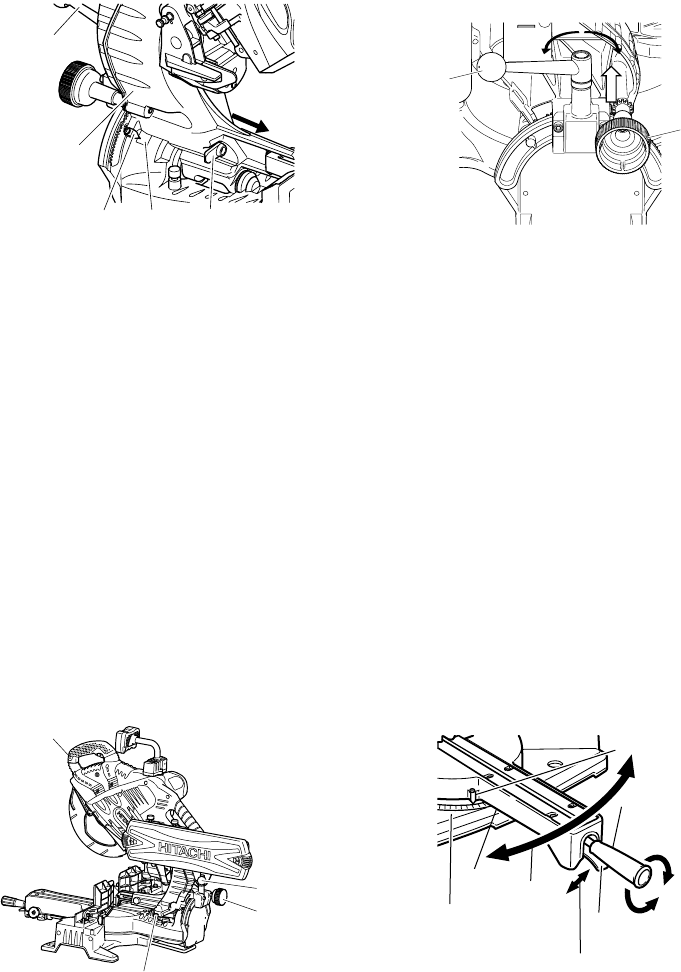
9. Miter cutting procedures
(1) Loosen the side handle and pull up the lever for angle
stoppers. Then, adjust the turntable until the indicator
aligns with desired setting on the miter scale (Fig. 36).
Fig. 36
Knob (B)
Clamp lever
Tighten
Loosen
Miter scale
Indicator
(For miter scale)
Side handle
Tighten
Loosen
Lever
Pull up
Turntable
Turn the
turntable
03Eng_C12LSH_Eng 4/26/07, 5:32 PM15