


7
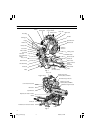
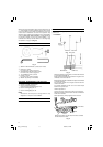
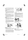
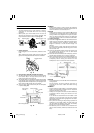
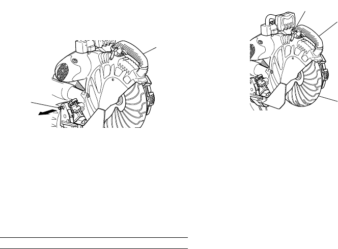
2. Releasing the locking pin
When the power tool is prepared for shipping, its main
parts are secured by a locking pin.
Move the handle slightly so that the locking pin can
be disengaged.
Fig. 6
NOTE
Lowering the handle slightly will enable you to
disengage the locking pin more easily and safely.
The lock position of the locking pin is for carrying and
storage only.
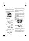
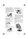
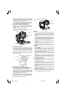
3. Installing the dust bag, holder, stopper and vises
(The holder and stopper are optional accessories.)
Attach the dust bag and vise assembly as indicated
in Fig. 1 and Fig. 2.
BEFORE USING
1. Make sure the power source is appropriate for the
tool.
WARNING
Never connect the power tool unless the available AC
power source is of the same voltage as that specified
on the nameplate of the tool.
Never connect this power tool to a DC power source.
2. Make sure the trigger switch is turned OFF.
WARNING
If the power cord is connected to the power source
with the trigger switch turned ON the power tool will
start suddenly and can cause a serious accident.
3. Check the saw blade for visible defects.
Confirm that the saw blade is free of cracks or other
visible damage.
4. Confirm that the saw blade is attached securely to
the power tool.
Using the supplied 17 mm box wrench, tighten the
10 mm bolt on the saw blade spindle to secure the
saw blade.
For details, see Fig. 55-a, Fig. 55-b, Fig. 55-c and Fig.
55-d in the section on “SAW BLADE MOUNTING AND
DISMOUNTING”.
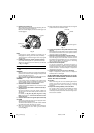
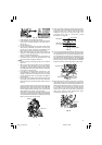
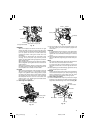
5. Check to see that the lower guard operates smoothly
CAUTION
This slide compound miter saw is equipped with a
saw head lock as safety device.
To lower the saw head to cut, the lock must be released
by pressing the lever (A) with your thumb.
(1) When you push down the handle while pushing the
lever (A), check that the lower guard revolves
smoothly (Fig. 7).
Pull
Locking pin
Handle
Lower guard
Fig. 7
6. Confirm the position of the spindle lock before using
the tool.
After installing the saw blade, confirm that the spindle
lock has been returned to the retract position before
using the power tool (see Fig. 2).
7. Check the lower limit position of the Saw Blade.
Although it was adjusted before shipment, carefully
check the height of the saw blade. Confirm that the
saw blade can be lowered 9 mm to 11 mm below the
table insert. For details, see the section on “Checking
the saw blade lower limit position”.
8. Check the Power Receptacle.
To prevent overheating, accidental stopping or
intermittent operation, confirm that the power cord
plug fits properly in the electrical receptacle and does
not fall out after it is inserted. Repair or replace the
receptacle if it is faulty.
9. Confirm the tool’s power cord is not damaged.
Repair or replace the power cord if an inspection
indicates that it is damaged
AFTER CONNECTING THE POWER PLUG TO AN AP-
PROPRIATE AC POWER SOURCE, CHECK THE OPERA-
TION OF THE TOOL AS FOLLOWS:
10. Trial Run
After confirming that no one is standing behind, the
power tool start and confirm that no operating
abnormalities exist before attempting a cutting
operation.
11. Inspect the rotating stability of the saw blade.
For precise cutting, rotate the saw blade and check
for deflection to confirm that the blade is not
noticeably unstable; otherwise vibrations might occur
and cause an accident.
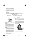
Lever (A)
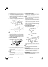
(2) Next, check that the lower guard returns to the original
position when the handle is raised.
Handle
03Eng_C12LSH_Eng 4/26/07, 5:32 PM7