


8
BEFORE CUTTING
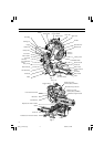
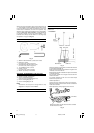
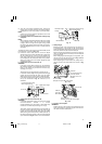
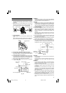
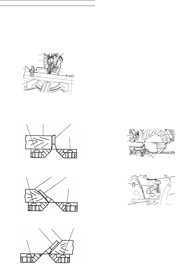
1. Cutting a groove on the guard
Holder (A) has a guard (see Fig. 8) into which a groove
must be cut.
Loosen the 6 mm knob bolt to retract the guard
slightly. After placing a suitable wooden piece to sit
on the fence and the table surfaces, fix it with the vise
assembly.
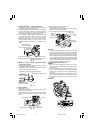
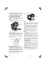
After the switch has been turned on and the saw blade
has reached maximum speed, slowly lower the handle
to cut a groove on the guard.
Fig. 8
CAUTION
Do not cut the groove too quickly; otherwise the guard
might become damaged.
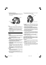
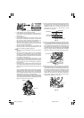
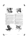
2. Positioning the table insert
[Right angle cutting]
Fig. 9-a
[Left bevel angle cutting]
Fig. 9-b
[Right bevel angle cutting]
Fig. 9-c
Table inserts are installed on the turntable. When
shipping the tool from the factory, the table inserts
are so fixed that the saw blade does not contact them.
The burr of the bottom surface of the workpiece is
remarkably reduced, if the table insert is fixed so that
the gap between the side surface of the table insert
and the saw blade will be minimum. Before using the
tool, eliminate this gap in accordance with the
following procedure.
(1) Right angle cutting
Loosen the three 5 mm machine screws, then secure
the left side table insert and temporarily tighten the 5
mm machine screws of both ends. Then fix a
workpiece (about 200 mm wide) with the vise
assembly and cut it off. After aligning the cutting
surface with the edge of the table insert, securely
tighten the 5 mm machine screws of both ends.
Remove the workpiece and securely tighten the 5 mm
center machine screw. Adjust the right hand table
insert in the same way.
(2) Left and right bevel angle cutting
Adjust the table insert in the manner shown in Fig. 9-
b and Fig. 9-c following the same procedure for right
angle cutting.
CAUTION
After adjusting the table insert for right angle cutting,
the table insert will be cut to some extent if it is used
for bevel angle cutting.
When bevel cutting operation is required, adjust the
table insert for bevel angle cutting.
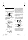
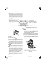
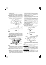
3. Checking the saw blade lower limit position
Fig. 10-a
Fig. 10-b
Check that the saw blade can be lowered 9 mm to 11
mm below the table insert as shown in Fig. 10-a.
When you replace a saw blade with a new one, adjust
the lower limit position so that the saw blade will not
cut the turntable or complete cutting cannot be done.
To adjust the lower limit position of the saw blade,
follow the procedure (1) indicated below. (Fig. 10-b)
Furthermore, when changing the position of a 8 mm
depth adjustment bolt that serves as a lower limit
position stopper of the saw blade.
Fence (A)
6 mm knob bolt
Holder (A)
Guard
Fence (B)
Workpiece
Vise assembly
Handle
Saw blade
Workpiece
Table insert
5 mm machine
screw
Saw blade
Table insert
Workpiece
5 mm machine
screw
Saw blade
Table insert
Saw blade
Workpiece
5 mm machine
screw
Gear case
8 mm depth
adjustment
bolt
Saw blade
Turntable
Hinge
8 mm depth
adjustment
bolt
Turn
Gear case
Hinge
03Eng_C12LSH_Eng 4/26/07, 5:32 PM8