


9
(1) Turn the 8 mm depth adjustment bolt, change the
height where the bolt head and the hinge contacts,
and adjust the lower limit position of the saw blade.
NOTE
Confirm that the saw blade is adjusted so that it will
not cut into the turntable.
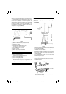
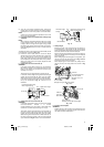
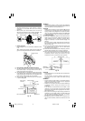
4. Lower limit position of saw blade when cutting a large
workpiece
NOTE
When cutting a workpiece exceeding 107 mm in height
in right-angle cutting or 70 mm in left bevel angle
cutting or 45 mm in right bevel angle cutting, adjust
the lower limit position so that the base of the motor
head (see Fig. 10-a) will not come in contact with the
workpiece.
To adjust the lower limit position of the saw blade, follow
the procedure (1) shown in Fig. 10-a.
(1) Lower the motor head, and turn the 8 mm depth
adjustment bolt and make adjustments so that there
can be a clearance of 2 mm to 3 mm between the
lower limit position of the motor head and the top of
the workpiece at the saw blade's lower limit position
where the head of the 8 mm depth adjustment bolt
contacts the hinge.
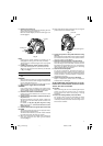
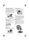
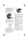
5. Confirmation for use of sub fence (A)
WARNING
In the case of right bevel cutting, turn the sub fence
(A) clockwise. Unless it is turned clockwise, the main
body or saw blade may contact the sub fence (A),
resulting in an injury.
This power tool is equipped with a sub fence (A).
In the case of direct angle cutting and left bevel angle
cutting, use the sub fence (A). Then, you can realize
stable cutting of the material with a wide back face.
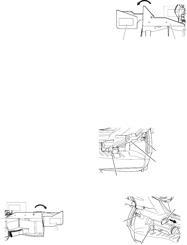
In the case of right bevel cutting, raise the sub fence
(A) up as illustrated in Fig. 11 and then turn it
clockwise.
Fig. 11
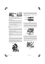
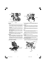
6. Confirmation for use of sub fence (B)
WARNING
In the case of left bevel cutting, turn the sub fence (B)
counterclockwise. Unless it is turned
counterclockwise, the main body or saw blade may
contact the sub fence (B), resulting in an injury.
This power tool is equipped with a sub fence (B). In
the case of direct angle cutting and right bevel angle
cutting, use the sub fence (B). Then, you can realize
stable cutting of the material with a wide back face. In
the case of left bevel cutting, raise the sub fence (B)
up as illustrated in Fig.12 and turn it counterclockwise.
Fig. 12
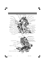
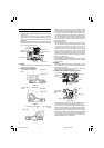
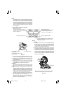
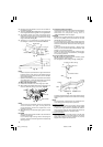
7. Oblique angle
Before the power tool is shipped from the factory, it
is adjusted for 0°, right angle, left 45° bevel cutting
angle and right 45° bevel cutting angle with the 8 mm
set screw, 8 mm bolt (A) and 8 mm bolt (B).
When changing the adjustment, change the height of
the 8 mm set screw, 8 mm bolt (A), or 8 mm bolt (B)
by turning them.
When changing the bevel angle to the right 45°, pull
the set pin (A) on the direction shown in Fig. 13-b and
incline the motor head to the right.
When adjusting the motor head to 0°, always return
the set pin (A) to its initial position as shown in Fig.
13-b.
Fig. 13-a
Fig. 13-b
8. Securing the workpiece
WARNING
Always clamp or vise to secure the workpiece to the
fence; otherwise the workpiece might be thrust from
the table and cause bodily harm.
Left bevel angle
cutting
Right bevel angle cutting
Direct angle cutting
Fence (B)
Turn
Sub fence (B)
Sub fence (A)
Right bevel angle
cutting
Turn
Left bevel angle cutting
Direct angle cutting
Fence (A)
8 mm bolt (A)
(Stopper for left 45° bevel angle)
Indicator
(For right
bevel scale)
Pull
Set pin (A)
8 mm bolt (B)
(Stopper for right 45° bevel angle)
Indicator
(For left bevel scale)
8 mm set screw
(Stopper for 0° not
shown)
03Eng_C12LSH_Eng 4/26/07, 5:32 PM9