


Switch A
Mgmt
Mod
Switch B
12
3
4
56
7
8910
11 12
13
14
Switch A
Mgmt
Mod
Switch B
12
3
4
56
7
8910
11 12
13
14
Switch A
Mgmt
Mod
Switch B
12
3
4
56
7
8910
11 12
13
14
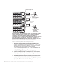
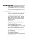
L2 Switch
L2+ Switch
L2+ Switch
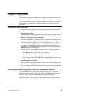
Multiport aggregation group
1 Gbps or 100 Mbps links
10/100 Mbps
management
links
Dual
external
switches
Establishment
backbone
IBM Director
- Chassis management
- Application deployment
- Internal switches
Network administrator
- Infrastructure
management
- Network hardware
and software
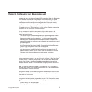
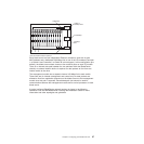
In this configuration, each BladeCenter unit contains two Ethernet switch modules
and one management module. The external ports on the switch modules are
configured for multi-port link aggregation groups, or trunks, as are the
corresponding ports on the attaching external LAN switches. Additionally, every port
in the switch module in I/O-module bay 1 (switch A in this illustration) in the
BladeCenter units is connected to the same external LAN switch and every port in
the switch module in I/O-module bay 2 (switch B in this illustration) in the
BladeCenter units is connected to the second external LAN switch.
Observe the following guidelines when creating this topology:
1. The external ports on the BladeCenter switch modules are designed for
point-to-point, full-duplex operation to a compatible LAN switch or router.
Configure a corresponding multi-port link aggregation group, or trunk, in both
the switch module and the attaching LAN switch prior to installing the cables.
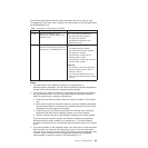
The connection options are as follows, in order of preference:
v Multi-port Link Aggregation Group or Trunk, 1 Gbps (1000 Mbps) per port
v Single-uplink port, 1 Gbps
v Multi-port Link Aggregation Group or Trunk, 100 Mbps per port
2. Connect the management module 10/100 Mbps Ethernet port to a separate
Layer 2 network if possible, for the best security. If a separate network is not
available, you can attach the Ethernet ports of the management module and
switch modules to the same Layer 2 network.
3. Avoid network configurations that could lead to data loops, if possible. Loops
will be created if you connect multiple ports from the same switch module to the
same Layer 2 network device without first enabling link aggregation. If you
implement configurations that include data loops, it is essential that you enable
Spanning Tree Protocol on the I/O module external ports.
28 BladeCenter E Type 8677 and 1881: Hardware Maintenance Manual and Troubleshooting Guide