


MAINTENANCE
35
enhttp://air.ingersollrand .com
COOLER CLEANING PROCEDURE
1. Stop the machine, electrically isolate and vent all trapped pressure.
2. Remove the rear cover to obtain access to the cooler.
3. Clean the cooler, blowing debris outward away from unit.
4. Rebuild in reverse order.
SETTING THE PRESSURE TRANSDUCER (PT)
TO CHECK THE MAXIMUM DISCHARGE PRESSURE
(Pressure transducer upper trip point)
Slowly close the isolation valve located adjacent to the compressor.
Observe the rise in pressure and ensure that the pressure transducer
opens at the correct Maximum discharge pressure.
The maximum discharge pressure is shown on the machine data plate.
DO NOT exceed these gures.
The compressor will stop once the system pressure rises to this
pressure.
TO CHECK THE TARGET PRESSURE
Observe the line pressure fall and note the point at which the
pressure transducer closes (and starts the compressor).
TO ADJUST THE TARGET PRESSURE
Remove the airend enclosure panel and locate the POT. Turn the POT
adjuster knob clockwise to increase the set point or anti −clockwise to
decrease it.
TO CONVERT UNIT FROM VARIABLE SPEED MODE TO FIXED
SPEED MODE.
Remove the airend enclosure panel and locate the toggle switch. Since
the switch is a 2 −position , simply toggle between position to vary the
mode.
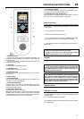
ELECTRIC DRAIN VALVE
PRODUCT DESCRIPTION
The Electric Drain Valve removes condensed water and oil from the air
receiver tank. Additional drains may be installed throughout your
compressed air system, including aftercoolers, lters, drip legs and
dryers.
The Electric Drain Valve operates on a timer which can be set to
automatically drain the air receiver tank at operator −determined
intervals.
Key features include:
• 100% continuous duty
• NEMA 4 (IP 55) enclosure
• Adjustable time on (0.5 − 10 seconds)
• Adjustable time o (0.5 − 45 minutes)
• Stainless steel operator
• LED to indicate electrical power is on
• LED to indicate valve is open
• Manual override
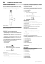
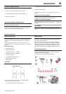
OPERATION
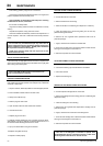
1. Open the strainer ball valve.
Strainer Ball Valve.
OPEN CLOSED
2. Set the “time o” and “time on” knobs. See TIMER SETTINGS
(below) for an explanation of the settings.
3. During compressor operation, check for air leaks.
TIMER SETTINGS
The “time o” setting determines the interval between cycles from 30
seconds to 45 minutes. The “time on” setting determines the actual time
the compressor drains condensate.
The timer’s cycle rate and drain opening time should be adjusted to
open just long enough to discharge the condensate. The timer is
properly set when it opens and discharges condensate and then vents
air for approximately one second before closing. Adjustments may be
made depending on many factors, including humidity and duty cycle.
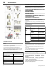
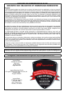
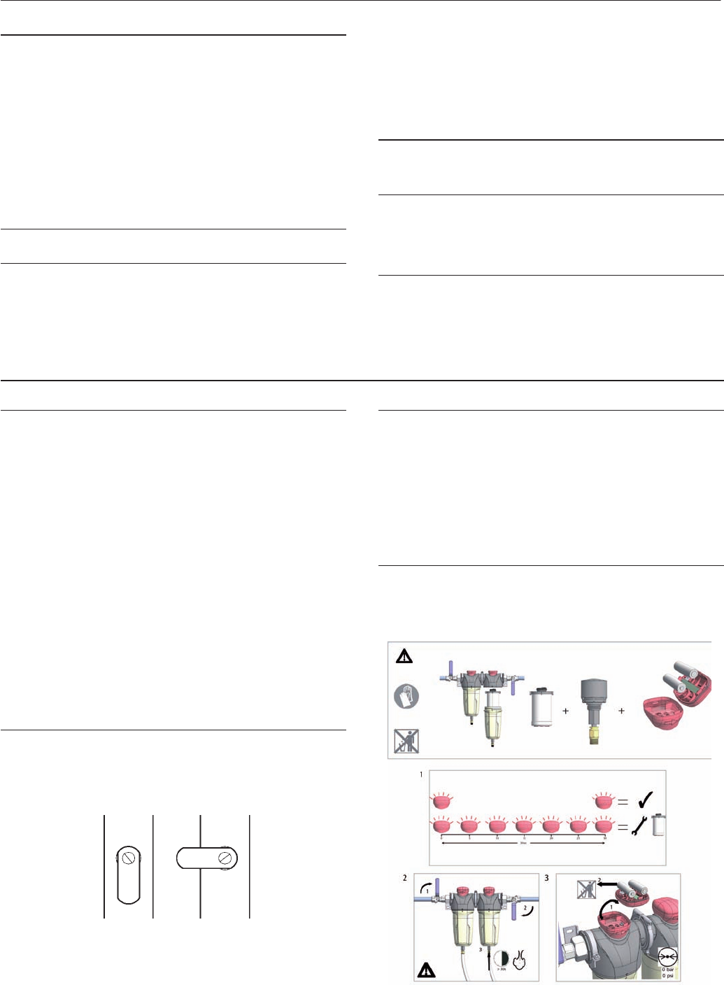
AIR FILTER MAINTENANCE
In order to ensure optimum compressed air quality the lter element
should be replaced as follows. (Used lter elements must be disposed
of in accordance with local regulations.)
Use only genuine Ingersoll Rand replacement elements.