


$)./''/$*)
+*2 -21 V
$)+0/*)) /$*)
*DBO7GK7B?<?;:;B;9JH?9?7DI>EKB:
9EDD;9J J>; ?DFKJ B;7:I JE J>;
+*2 -21 VEDD;9J?EDI
I>EKB:8;C7:;?D799EH:7D9;M?J>
7BB BE97B7D: D7J?ED7B;B;9JH?97B
9E:;I7D:J>;9EDD;9J?ED:?7=H7CBE97J;:EDJ>;
?DI?:; E<J>;H;9EDD;9J799;II :EEH E< J>;
C79>?D; !7?BKH; JE :EIEC7OH;IKBJ?D8E:?BO
?D@KHOEH:;7J>
------------------------------------------------------------------------
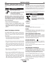
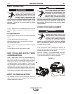
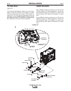
A 15 ft. power cord is provided and wired into the
machine. Follow the power cord connection instruc-
tions.
!EH.?D=B;+>7I;$DFKJ
Connect green lead to ground per National Electrical
Code.
Connect black and white leads to power.
Wrap red lead with tape to provide 600V insulation.
!EH/>H;;+>7I;$DFKJ
Connect green lead to ground per National Electric
Code.
Connect black, red and white leads to power.
$)+0/ !0. ) .0++'4 2$-
*).$ -/$*).
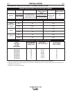
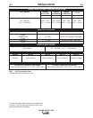
Refer to Specification Section for recommended fuse,
wire sizes and type of the copper wires. Fuse the
input circuit with the recommended super lag fuse or
delay type breakers (also called "inverse time" or
"thermal/magnetic" circuit breakers). Choose input
and grounding wire size according to local or national
electrical codes. Using input wire sizes, fuses or cir-
cuit breakers smaller than recommended may result in
"nuisance" shut-offs from welder inrush currents, even
if the machine is not being used at high currents.
$)+0/1*'/" . ' /$*)
The POWER WAVE® C300 automatically adjusts to
work with different input voltages. No reconnect
switches settings are required.
/>;+*2 -21 V *)*!!
IM?J9>?I DEJ?DJ;D:;:7I 7I;HL?9;
:?I9EDD;9J<EHJ>?I;GK?FC;DJ*DBO
7 GK7B?<?;: ;B;9JH?9?7DI>EKB:9ED
D;9JJ>;?DFKJ B;7:I JEJ>; +*2 -
21 VEDD;9J?EDII>EKB:
8;C7:;?D799EH:7D9;M?J>7BBBE97B7D:D7J?ED7B
;B;9JH?97B9E:;I7D:J>;9EDD;9J?ED:?7=H7CBE97J
;:EDJ>;?DI?:;E<J>;H;9EDD;9J799;II:EEHE<
J>;C79>?D;!7?BKH;JE:EIEC7OH;IKBJ?D8E:?BO
?D@KHOEH:;7J>
------------------------------------------------------------------------
+*2 -*-- +' ( )/
*DBO 7 GK7B?<?;: ;B;9JH?9?7DI>EKB:
9EDD;9J J>; ?DFKJ B;7:I JE J>;
+*2 -21 VEDD;9J?EDI
I>EKB:8;C7:;?D799EH:7D9;M?J>
7BB BE97B7D:D7J?ED7B ;B;9JH?97B
9E:;I 7D:J>;9EDD;9J?ED :?7=H7C
BE97J;: ED J>;?DI?:;E<J>;H;9EDD;9J799;II
:EEHE<J>;C79>?D;!7?BKH;JE:EIEC7OH;IKBJ
?D8E:?BO?D@KHOEH:;7J>
------------------------------------------------------------------------
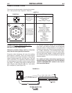
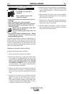
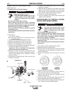
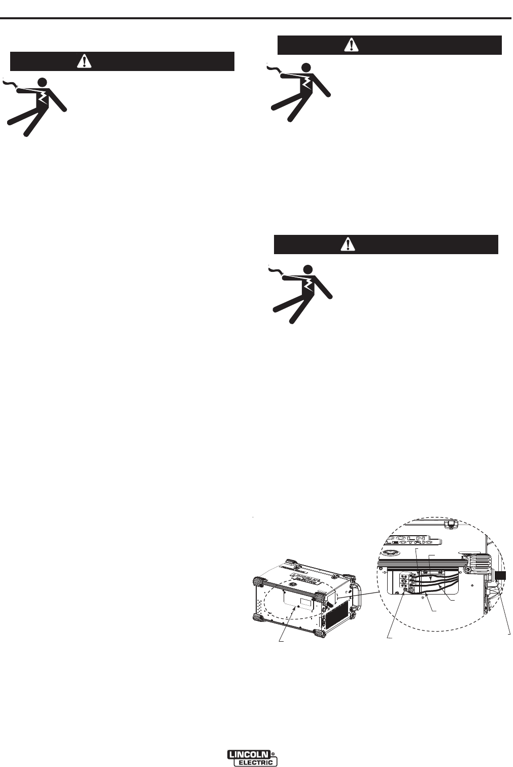
If the input power cord is damaged or needs to be
replaced an input power connection block is located in
the access panel under the wire spool.
ALWAYS CONNECT THE POWERWAVE GROUND-
ING LUG (LOCATED INSIDE THE ACCESS PANEL)
TO A PROPER SAFETY (EARTH) GROUND.
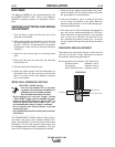
!$"0-
2-)$)"
2-)$)"
2-)$)"
GROUND LUG
BLACK
RED
WHITE
GREEEN
INPUT CORD
ACCESS PANEL
GROUND LUG
BLACK
RED
WHITE
GREEEN
INPUT CORD
ACCESS PANEL