


*+ -/$*)
(&$)" 2 ' 2$/# 21 !*-(
/ #)*'*"4+*2 -.*0- .
(&$)"2 '
/>;I;HL?9;78?B?JOE<7FHE:K9JEHIJHK9JKH;KJ?B?P
?D=J>;M;B:?D=FHE=H7CI?I7D:CKIJ8;J>;IEB;
H;IFEDI?8?B?JOE< J>; 8K?B:;HKI;H (7DO L7H?78B;I
8;OED: J>; 9EDJHEB E< />; '?D9EBD B;9JH?9
ECF7DO 7<<;9JJ>; H;IKBJI E8J7?D;:?D7FFBO?D=
J>;I;FHE=H7CI/>;I; L7H?78B;I?D9BK:;8KJ 7H;
DEJB?C?J;:JEM;B:?D=FHE9;:KH;FB7J;9>;C?IJHO
7D: J;CF;H7JKH; M;B:C;DJ:;I?=D <78H?97J?ED
C;J>E:I7D: I;HL?9;H;GK?H;C;DJI/>; 7L7?B78B;
H7D=;E<7M;B:?D=FHE=H7CC7O DEJ 8;IK?J78B;
<EH7BB7FFB?97J?EDI7D:J>;8K?B:KI;H?I7D:CKIJ
8;IEB;BO H;IFEDI?8B; <EHM;B:?D= FHE=H7CI;B;9
J?ED
---------------------------------------------------------------------
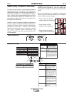
Choose the electrode material, electrode size, shield-
ing gas, and process (GMAW, GMAW-P etc.) appro-
priate for the material to be welded.
Select the weld mode that best matches the desired
welding process. The standard weld set shipped with
the Power Wave C300 encompasses a wide range of
common processes that will meet most needs. If a
special weld mode is desired, contact the local Lincoln
Electric sales representative.
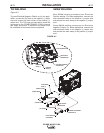
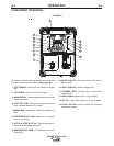
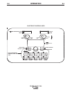
All adjustments are made through the user interface.
Because of the different configuration options your
system may not have all of the following adjustments.
Regardless of availability, all controls are described in
the following section ( See Figure B.4 Panel Controls
Used)
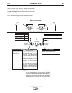
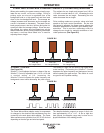
!$)$/$*)*!2 '$)"(* .
)*).4) -"$2 '$)"(* .
• A )EDIOD;H=?9 welding mode requires all welding
process variables to be set by the operator.
.4) -"$2 '$)"(* .
• A .OD;H=?9 welding mode offers the simplicity of
single knob control. The machine will select the cor-
rect voltage and amperage based on the wire feed
speed (WFS) set by the operator.
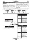
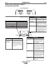
.$2 '$)"*)/-*'.
2 '(*
Selecting a weld mode determines the output charac-
teristics of the Power Wave power source. Weld
modes are developed with a specific electrode materi-
al, electrode size, and shielding gas. For a more com-
plete description of the weld modes programmed into
the Power Wave at the factory, refer to the 2;B:.;J
-;<;H;D9;"K?:; supplied with the machine or avail-
able at MMMFEM;HM7L;IE<JM7H;9EC.
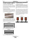
2$- ! .+ 2!.
In synergic welding modes (synergic CV, GMAW-P),
WFS is the dominant control parameter. The user
adjusts WFS according to factors such as wire size,
penetration requirements, heat input, etc. The Power
Wave then uses the WFS setting to adjust the voltage
and current according to settings contained in the
Power Wave.
In non-synergic modes, the WFS control behaves like
a conventional power source where WFS and voltage
are independent adjustments. Therefore, to maintain
proper arc characteristics, the operator must adjust
the voltage to compensate for any changes made to
the WFS.
(+.
In constant current modes, this control adjusts the
welding current.
1*'/.
In constant voltage modes, this control adjusts the
welding voltage.
/-$(
In pulse synergic welding modes, the Trim setting
adjusts the arc length. Trim is adjustable from 0.50 to
1.50. 1.00 is the nominal setting and is a good start-
ing point for most conditions.
0'/$(-
/(
*)/-*'
UltimArc
TM
Control allows the operator to vary the arc
characteristics from “soft” to “crisp”.
UltimArc™Control is adjustable from –10.0 to +10.0
with a nominal setting of 0.0.
+*2 -21 V
2-)$)"