


*+ -/$*)
+*2 -21 V
'0($)0("(2++0'. ($"
)"(2+++0'. *)+0'.
2 '$)"
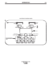
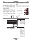
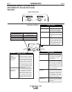
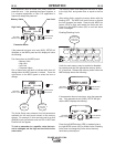
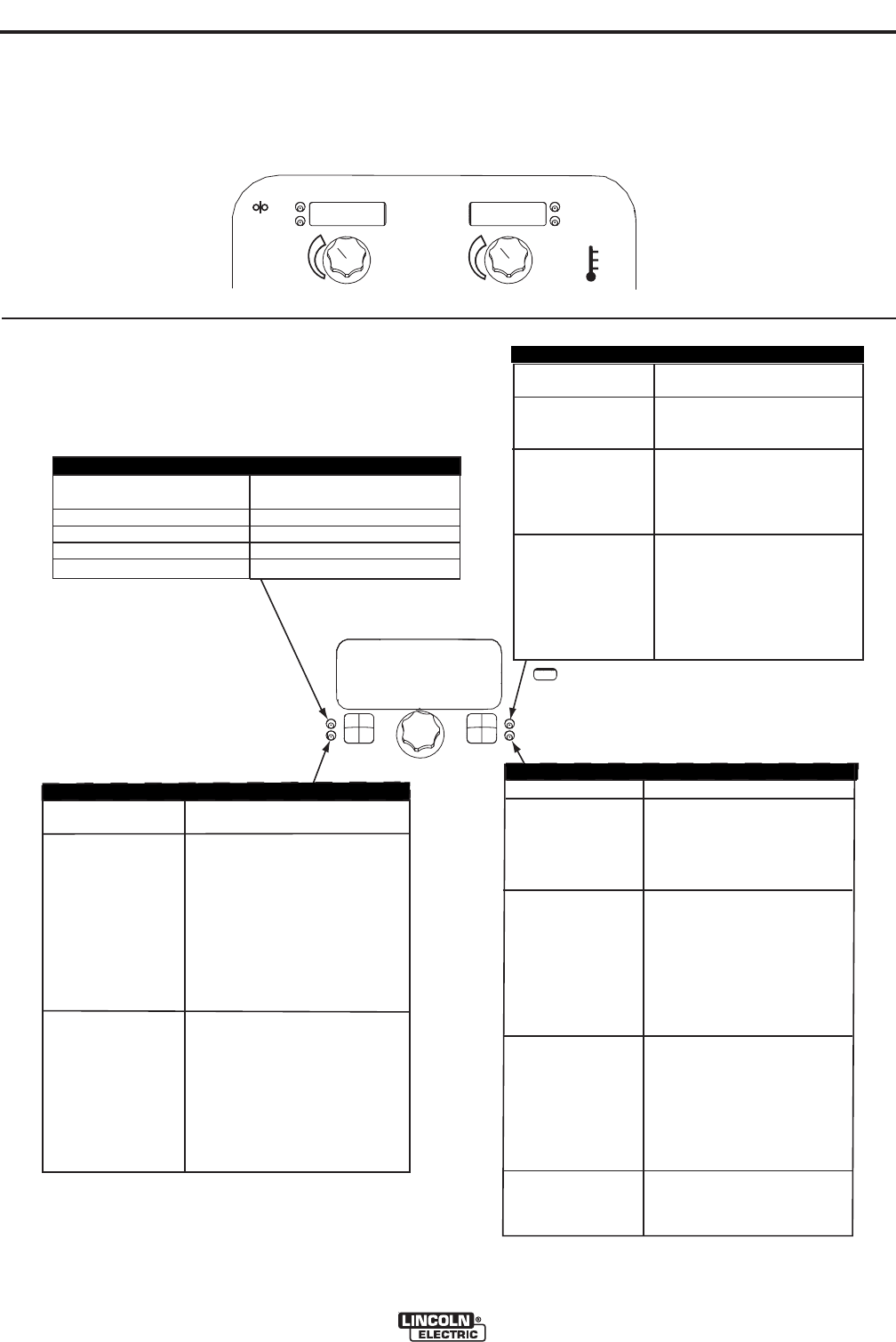
START OPTIONS
E
ND OPTIONS
SETUP
WELD MODE
UltimArc™ Control
Less
Deposition
More
Deposition
Shorter
Arc
Longer
Arc
+
+
AMPS
WFS
VOLTS
TRIM
220
1.06
72
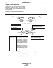
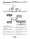
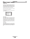
EFFECT / RANGE
PULSE
PULSE-ON-PULSE
FREQUENCY:
FREQ.MODULATION
(Low)-10.0 to
(High)+10.0
(Low)-10.0 to
(High)+10.0
DESCRIPTION
For Pulse -On-Pulse modes,
Arc controls changes the frequ-
ency modulation. The freque-
-ncy modulation controls the
spacing of the ripples in the
weld. Use low values for slow
travel speeds and wide welds,
and high values for fast travel
speeds and narrower welds.
For Pulse
modes, Arc Control
changes the pulsing frequency.
When the frequency changes,
the Power Wave system auto-
matically adjusts the back-
ground current to maintain a
similar heat input into the weld.
Low frequencies give more con-
trol over the puddle and high
frequencies minimize spatter.
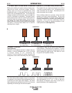
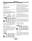
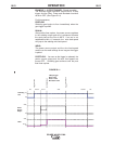
EFFECT
Postflow Time
RUN-INWFS:
.
Start Procedure
DESCRIPTION
Adjusts the time that shielding
gas
flows
after
the trigger is
pulled
and
prior to feeding wire.
Run-in sets the wire feed
speed from the time the trigger
is pulled until an arc is estab-
lished.
The Start Procedure controls
the WFS. Trim at a specified
time at the beginning of the
weld. During the start time, the
machine will ramp up or down
from the Start Procedure to the
preset Welding Procedure.
EFFECT
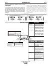
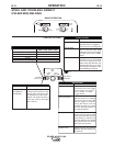
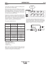
FUNCTION
ELECTRODE AND GAS
ALUMINUM 4043
ALUMINUM 4043
ALUMINUM 5356
ALUMINUM 5356
Ar
Ar
Ar
Ar
WIRE SIZE
0.035 3/64 1/16
149 72 74
98 99 100
152 76 78
101 102 103
WELD MODES
START OPTIONS
END OPTIONS
UltimArc™ Control
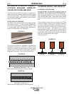
Aluminum 3/64"
Pulse 4043 Ar
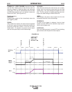
Spot Timer
Adjust the time welding will
continue even if the trigger
is still pulled. This option
has no effect in 4-Step
Trigger Mode.
Crater Procedure
Crater Procedure controls the
WFS and Volts for a specified
time at the end of the weld
after the trigger is released.
During the Crater time, the
machine will ramp up or down
from the Weld Procedure to
the Crater Procedure.
Burnback:
The burnback time is the
amount of time that the weld
output continues after the wire
stops feeding. It prevents the
wire from sticking in the puddle
and prepares the end of the
wire for the next arc start.
Postflow Time
Adjusts the time that shielding
gas flows after the welding out-
put turns off.
START OPTIONS
E
ND OPTIONS
SETUP
WELD MODE
UltimArc™ Control
Less
Deposition
More
Deposition
Shorter
Arc
Longer
Arc
+
+
AMPS
WFS
VOLTS
TRIM
220
1.06
72
EFFECT / RANGE
PULSE
PULSE-ON-PULSE
FREQUENCY:
FREQ.MODULATION
(Low)-10.0 to
(High)+10.0
(Low)-10.0 to
(High)+10.0
DESCRIPTION
For Pulse -On-Pulse modes,
Arc controls changes the frequ-
ency modulation. The freque-
-ncy modulation controls the
spacing of the ripples in the
weld. Use low values for slow
travel speeds and wide welds,
and high values for fast travel
speeds and narrower welds.
For Pulse
modes, Arc Control
changes the pulsing frequency.
When the frequency changes,
the Power Wave system auto-
matically adjusts the back-
ground current to maintain a
similar heat input into the weld.
Low frequencies give more con-
trol over the puddle and high
frequencies minimize spatter.
EFFECT
Postflow Time
RUN-IN WFS:
.
Start Procedure
DESCRIPTION
Adjusts the time that shielding
gas
flows
after
the trigger is
pulled
and
prior to feeding wire.
Run-in sets the wire feed
speed from the time the trigger
is pulled until an arc is estab-
lished.
The Start Procedure controls
the WFS. Trim at a specified
time at the beginning of the
weld. During the start time, the
machine will ramp up or down
from the Start Procedure to the
preset Welding Procedure.
EFFECT
FUNCTION
ELECTRODE AND GAS
ALUMINUM 4043
ALUMINUM 4043
ALUMINUM 5356
ALUMINUM 5356
Ar
Ar
Ar
Ar
WIRE SIZE
0.035 3/64 1/16
149 72 74
98 99 100
152 76 78
101 102 103
WELD MODES
START OPTIONS
END OPTIONS
UltimArc™ Control
Aluminum 3/64"
Pulse 4043 Ar
Spot Timer
Adjust the time welding will
continue even if the trigger
is still pulled. This option
has no effect in 4-Step
Trigger Mode.
Crater Procedure
Crater Procedure controls the
WFS and Volts for a specified
time at the end of the weld
after the trigger is released.
During the Crater time, the
machine will ramp up or down
from the Weld Procedure to
the Crater Procedure.
Burnback:
The burnback time is the
amount of time that the weld
output continues after the wire
stops feeding. It prevents the
wire from sticking in the puddle
and prepares the end of the
wire for the next arc start.
Postflow Time
Adjusts the time that shielding
gas flows after the welding out-
put turns off.
.$*+ -/$*)
*)/-*'*+/$*).