


*+ -/$*)
"(2($".4) -"$2 '$)"
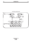
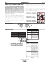
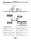
For each wire feed speed, a corresponding voltage is
preprogrammed into the machine. The nominal pre-
programmed voltage is the best average voltage for a
given wire feed speed, but may be adjusted to prefer-
ence. When the wire feed speed changes, the Power
Wave automatically adjusts the voltage level corre-
spondingly to maintain similar arc characteristics
throughout the WFS range.
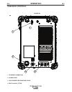
UltimArc™Control, adjusts the apparent inductance of
the wave shape. The UltimArc™Control adjustment is
similar to the “pinch” function in that it is inversely pro-
portional to inductance. Therefore, increasing
UltimArc™Control greater than 0.0 results in a crisper
arc (more spatter) while decreasing the
UltimArc™Control to less than 0.0 provides a softer
arc (less spatter).
+*2 -21 V
S
TART OPTIONS
END OPTIONS
SETUP
WELD MODE
UltimArc™ Control
L
ess
Deposition
More
D
eposition
Shorter
Arc
Longer
A
rc
+
+
AMPS
W
FS
VOLTS
TRIM
220
26.4
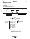
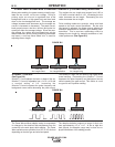
EFFECT / RANGE
PINCH EFFECT
(-10.0 to +10.0)
DESCRIPTION
-
E
FFECT
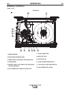
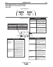
Preflow Time
Run-in WFS:
Start Procedure
D
ESCRIPTION
A
djusts the time
that shielding
gas
f
lows
a
fter the
t
rigger
i
s
p
ulled
and
prior to feeding.
Run-In sets the wire feed
speed from the time the trigger
is pulled until an arc is estab-
lished.
The Start Procedure controls
the WFS, Volts at a specified
time at the beginning of the
weld. During the start time, the
machine will ramp up or down
from the Start Procedure to the
preset Welding Procedure.
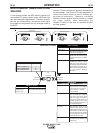
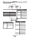
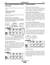
EFFECT
DESCRIPTION
Steel
Steel
Stainless
Stainless
Aluminum 4043
Aluminum 5356
E
LECTRODE AND GAS
CO
2
Ar(Mix)
Ar(Mix)
Ar/He/CO
2
Ar
Ar
W
IRE SIZE
0.030 0.035 0.045 0.052
---10 20 24
94 11 21 25
61 31 41 ---
63 33 43 ---
--- 148 71 ---
--- 151 75 ---
WELD MODE
UltimArc™ Control
END OPTIONS
S
TART OPTIONS
Pinch controls the arc characte-
-ristics when short-arc welding.
STEEL .035"
CV CO2
10
Spot Timer
Adjust the time welding will
continue even if the trigger
is still pulled. This option
has no effect in 4-Step
Trigger Mode.
Crater Procedure
Crater Procedure controls the
WFS and Volts for a specified
time at the end of the weld
after the trigger is released.
During the Crater time, the
machine will ramp up or down
from the Weld Procedure to
the Crater Procedure.
Burnback:
The burnback time is the
amount of time that the weld
output continues after the wire
stops feeding. It prevents the
wire from sticking in the puddle
and prepares the end of the
wire for the next arc start.
Postflow Time
Adjusts the time that shielding
gas flows after the welding out-
put turns off.
S
TART OPTIONS
END OPTIONS
SETUP
WELD MODE
UltimArc™ Control
L
ess
Deposition
More
D
eposition
Shorter
Arc
Longer
A
rc
+
+
AMPS
W
FS
VOLTS
TRIM
220
26.4
EFFECT / RANGE
PINCH EFFECT
(-10.0 to +10.0)
DESCRIPTION
-
E
FFECT
Preflow Time
Run-in WFS:
Start Procedure
D
ESCRIPTION
A
djusts the time
that shielding
gas
f
lows
a
fter the
t
rigger
i
s
p
ulled
and
prior to feeding.
Run-In sets the wire feed
speed from the time the trigger
is pulled until an arc is estab-
lished.
The Start Procedure controls
the WFS, Volts at a specified
time at the beginning of the
weld. During the start time, the
machine will ramp up or down
from the Start Procedure to the
preset Welding Procedure.
EFFECT
DESCRIPTION
Steel
Steel
Stainless
Stainless
Aluminum 4043
Aluminum 5356
E
LECTRODE AND GAS
CO
2
Ar(Mix)
Ar(Mix)
Ar/He/CO
2
Ar
Ar
W
IRE SIZE
0.030 0.035 0.045 0.052
--- 10 20 24
94 11 21 25
61 31 41 ---
63 33 43 ---
--- 148 71 ---
--- 151 75 ---
WELD MODE
UltimArc™ Control
END OPTIONS
S
TART OPTIONS
Pinch controls the arc characte-
-ristics when short-arc welding.
STEEL .035"
CV CO2
10
Spot Timer
Adjust the time welding will
continue even if the trigger
is still pulled. This option
has no effect in 4-Step
Trigger Mode.
Crater Procedure
Crater Procedure controls the
WFS and Volts for a specified
time at the end of the weld
after the trigger is released.
During the Crater time, the
machine will ramp up or down
from the Weld Procedure to
the Crater Procedure.
Burnback:
The burnback time is the
amount of time that the weld
output continues after the wire
stops feeding. It prevents the
wire from sticking in the puddle
and prepares the end of the
wire for the next arc start.
Postflow Time
Adjusts the time that shielding
gas flows after the welding out-
put turns off.
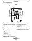
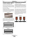
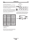
.OD;H=?91 programs feature an ideal voltage best
suited for most procedures. Use this voltage as a
starting point and adjust if needed for personal prefer-
ences.
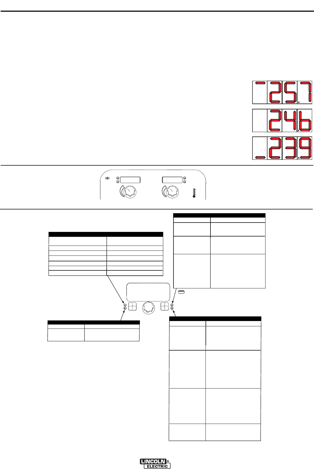
When the voltage knob is rotated, the display will
show an upper or lower bar indicating if the voltage is
above or below the ideal voltage.
• Preset voltage above ideal
voltage. (upper bar displayed)
• Preset voltage at ideal
voltage. (no bar displayed)
• Preset voltage below ideal
voltage. (lower bar displayed)
.$*+ -/$*)
*)/-*'*+/$*).