


$)./''/$*)
+*2 -21 V
'*$)".+**'.*!2$-
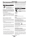
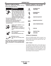
U&;;F>7D:I>7?H9BEJ>?D=7D:JEEBI7M7O<HEC
HEJ7J?D=;GK?FC;DJ
UEDEJM;7H=BEL;IM>;DJ>H;7:?D=
M?H;EH9>7D=?D=M?H;IFEEB
U*DBOGK7B?<?;:F;HIEDD;BI>EKB:?DIJ7BB
KI;EHI;HL?9;J>?I;GK?FC;DJ
------------------------------------------------------------------------
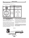
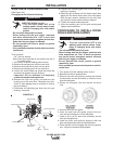
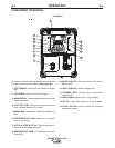
'E7:?D=JEB8\A=.FEEBI
A K468 spindle adapter permits 8” (203mm) O.D.
spools to be mounted on 2” (51mm) O.D. spindles.
1. Squeeze the release bar on the retaining collar and
remove it from the spindle.
2. Place the spindle adapter on the spindle, aligning
the spindle brake pin with the hole in the adapter.
3. Place the spool on the spindle and align the
adapter brake tab with one of the holes in the back
side of the spool. An indicator mark on the end of
the spindle shows the orientation of the brake tab.
Be certain the wire feeds off of the spool in the
proper direction.
4. Re-install the retaining collar. Make sure that the
release bar snaps out and that the retaining collar
fully engages the groove on the spindle.
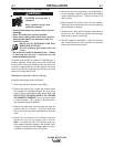
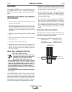
'E7:?D=JEB8\A=.FEEBI
1. Squeeze the release bar on the retaining collar and
remove it from the spindle.
2. Place the spool on the spindle, aligning the spindle
brake pin with one of the holes in the back side of
the spool. An indicator mark on the end of the spin-
dle shows the orientation of the brake holding pin.
Be certain the wire feeds off of the spool in the
proper direction.
3. Re-install the retaining collar. Make sure that the
release bar snaps out and that the retaining collar
fully engages the groove on the spindle
2-)$)"