


B-4
OPERATION
B-4
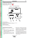
CONTROLS AND SETTINGS
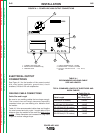
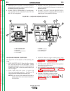
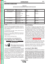
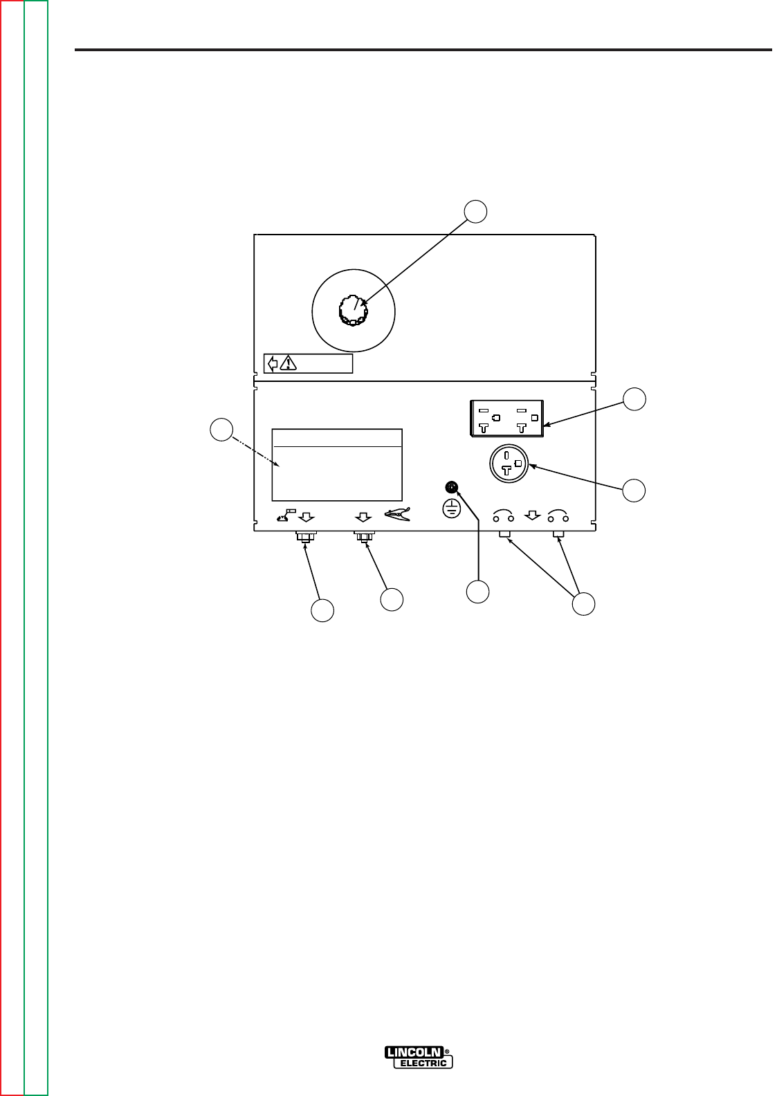
All generator/welder controls are located on the
Output Control Panel. Gasoline engine controls are
mounted on the engine. See Figures B.1 and B.2 and
the explanations that follow.
GENERATOR/WELDER CONTROLS
See Figure B.1 for the location of the following
features:
1. CURRENT CONTROL DIAL: Adjusts continuous
current output. The amperages on the dial
correspond to the average amperages needed for
specific Lincoln welder rods.
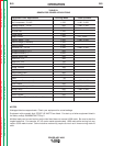
2. ELECTRODE SELECTION GUIDE: Provides
recommended electrode type, size, and welder
output setting based on the thickness of the
work.
3. WELD OUTPUT TERMINAL (TO ELECTRODE
HOLDER) WITH 1/2 - 13 FLANGE NUT: Provides
the connection point for either the electrode
holder or the work cable. (Because the POWER-
ARC 4000 is an AC output machine, either output
terminal can be used for either cable.)
4. WELD OUTPUT TERMINAL (TO WORK) WITH 1/2
- 13 FLANGE NUT: Provides the connection
point for either the electrode holder or the work
cable. (Because the POWER-ARC 4000 is an AC
output machine, either output terminal can be
used for either cable.)
POWER-ARC 4000
Return to Section TOC Return to Section TOC Return to Section TOC Return to Section TOC
Return to Master TOC Return to Master TOC Return to Master TOC Return to Master TOC
POWER ARC 4000
ELECTRODE SELECTION GUIDE
80
90
100
70
AMPS
AMPS
AMPS
AMPS
WARNING
AMPS
125
GENERATOR
8
7
6
5
3
1
2
4
FIGURE B.1 – OUTPUT PANEL CONTROLS
1. CURRENT CONTROL DIAL
2. ELECTRODE SELECTION GUIDE
3. WELD OUTPUT TERMINAL (TO ELECTRODE HOLDER) WITH 1/2 - 13 FLANGE NUT
4. WELD OUTPUT TERMINAL (TO WORK) WITH 1/2 - 13 FLANGE NUT
5. GROUND STUD
6. 20 AMP CIRCUIT BREAKERS (2)
7. 20 AMP, 240 VOLT RECEPTACLE
8. 20 AMP, 120 VOLT DUPLEX RECEPTACLE