


F-12
TROUBLESHOOTING & REPAIR
F-12
POWER-ARC 4000
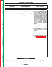
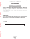
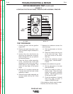
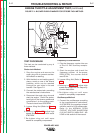
TEST PROCEDURE
1. With the 5/16” nut driver, remove
the 4 sheet metal screws that hold
the top cover to the control box.
Remove the top cover.
2. Start the machine and run it at high
idle. Set the output control (rheo-
stat) at the MAXIMUM or GENERA-
TOR setting.
3. Set the volt/ohmmeter at the DC
position.
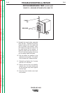
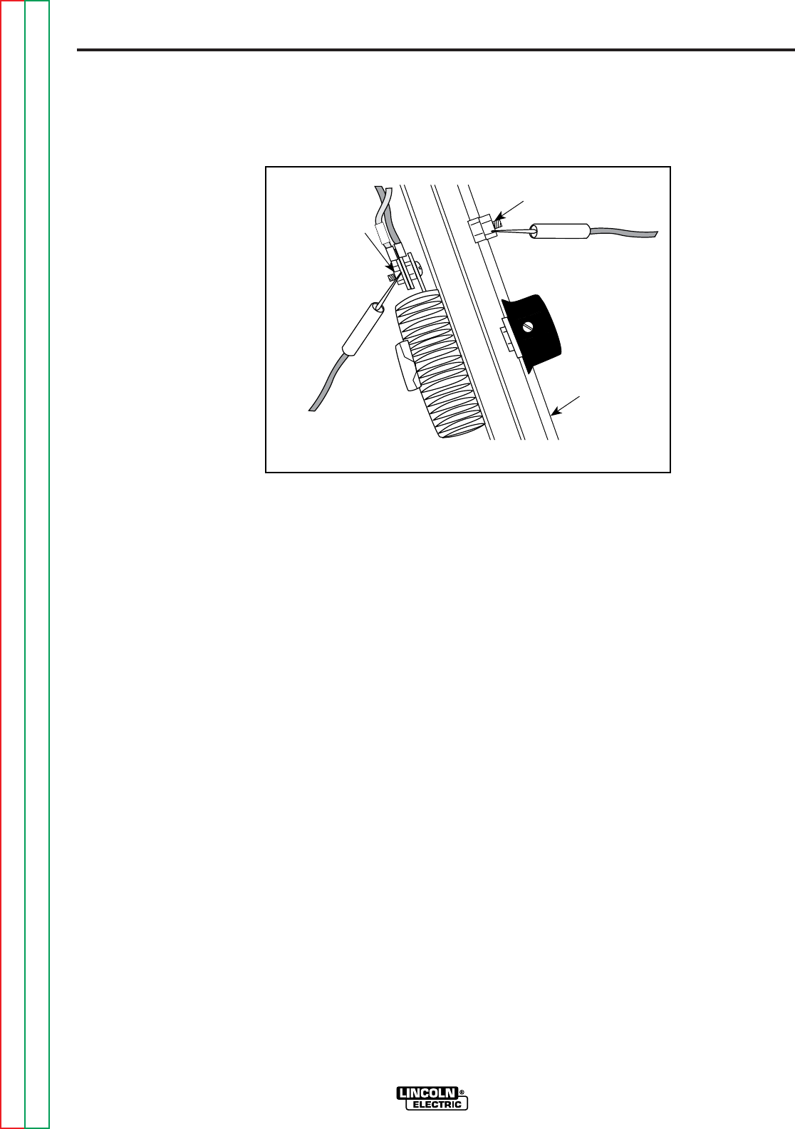
4. Place the positive probe on lead 200
where it connects at the back of the
rheostat. See Figure F.1 for loca-
tion. Place the negative probe on
the machine ground stud or any
other good, unpainted ground.
5. Check the voltage reading on the
volt/ohmmeter. It should read 45 -
48 VDC.
6. If the voltage is low or not present,
the generator field circuit is not
functioning correctly. Proceed with
the Rotor Resistance Test. C1, R1,
or D1 may also be faulty.
7. If rotor voltage is correct, the gener-
ator field is okay. Replace the top
cover on the control box. Tighten
the 4 sheet metal screws with the
5/16” nut driver.
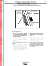
ROTOR VOLTAGE TEST (continued)
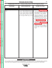
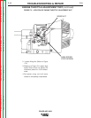
FIGURE F.1 - LOCATION OF LEAD 200A FOR ROTOR VOLTAGE TEST
Return to Section TOC Return to Section TOC Return to Section TOC Return to Section TOC
Return to Master TOC Return to Master TOC Return to Master TOC Return to Master TOC
200
LEAD 200
CONNECTION
GROUND STUD
OUTPUT PANEL