


Return to Section TOC Return to Section TOC Return to Section TOC Return to Section TOC
Return to Master TOC Return to Master TOC Return to Master TOC Return to Master TOC
E-2
THEORY OF OPERATION
E-2
POWER-ARC 4000
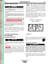
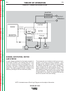
ENGINE, EXCITATION, ROTOR
AND STATOR
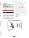
A small voltage developed by the engine magneto is
fed through a diode to the rotating field coil in the
rotor via a brush and slip ring configuration. This
excitation (“flashing”) voltage magnetizes the rotor
lamination. The rotor is mechanically coupled to the
engine. The rotating magnet induces a voltage in the
stationary windings of the main alternator (stator).
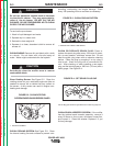
Three separate and isolated windings are incor-
porated in the stator lamination assembly. Each
winding set has a different number of turns, produc-
ing different magnitudes of AC output voltages. The
three windings are the weld winding, the auxiliary
power winding and the field feedback winding. The
field feedback winding provides rotor current during
machine operation. The output of the PowerArc 4000
is dependent on two criteria: the engine RPM and the
amount of current in the rotor winding.
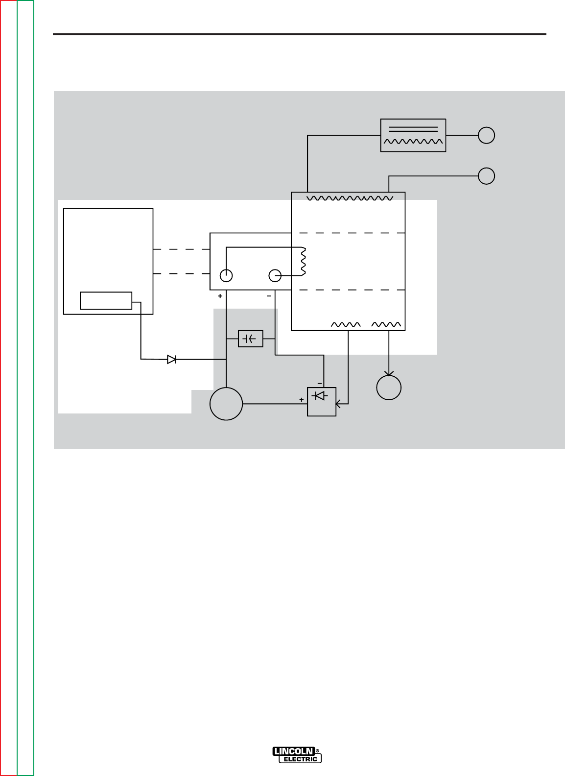
FIGURE E.2 – ENGINE, ROTOR AND STATOR
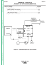
NOTE: Unshaded areas of Block Logic Diagram are the subject of discussion
ENGINE
STATOR
STATOR
ROTOR
REACTOR
BRIDGE
CAPACITOR
RHEOSTAT
115 AND 230VAC
RECEPTACLES
OUTPUT
TERMINALS
ROTATION
MECHANICAL
SLIP
RINGS
ROTOR
MAGNETO