


Return to Section TOC Return to Section TOC Return to Section TOC Return to Section TOC
Return to Master TOC Return to Master TOC Return to Master TOC Return to Master TOC
D-5
MAINTENANCE
D-5
POWER-ARC 4000
GENERATOR/WELDER MAINTENANCE
STORAGE: Store the POWER-ARC 4000 in clean,
dry, protected areas.
CLEANING: Blow out the generator and controls
periodically with low pressure air. Do this at least
once a week in particularly dirty areas.
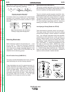
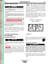
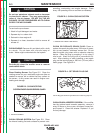
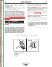
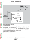
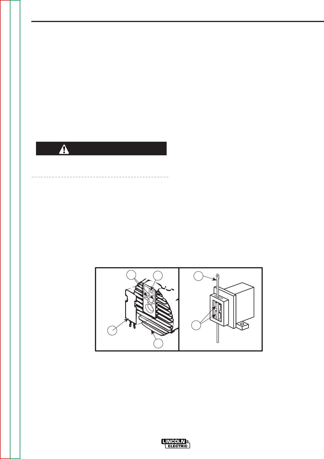
BRUSH REMOVAL AND REPLACEMENT: See
Figure D.5. It’s normal for the brushes and slip
rings to wear and darken slightly. Inspect the
brushes when a generator overhaul is necessary.
Remove the brushes and clean the slip rings with
fine grit emery paper. Refer to the Troubleshooting
chapter for Brush Removal and Replacement
Procedures.
Do not attempt to polish slip rings while engine
is running.
To reinstall the brushes, press them upward and
slide a cable tie or wooden stick through the brush
holder tabs. Install the brush holder into the bear-
ing end bracket and secure with the screws previ-
ously removed. Remove the cable tie or wooden
stick and the brushes will seat onto the slip rings.
RECEPTACLES: Keep the electrical receptacles in
good condition. Remove any dirt, oil, or other
debris from their surfaces and holes.
CABLE CONNECTIONS: Check the welding cable
connections at the weld output terminals often. Be
sure that the connections are always tight.
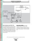
NOTE: Lincoln offers a rotor removal kit for any ser-
vice which requires removal of the rotor from the
engine. See the ACCESSORIES section for further
details.
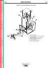
Removal of the engine/generator assembly from the
cradle can be achieved as follows:
• Remove the two 5/16-18 hex head cap screws
from the engine block via the access hole located
in the cradle cross support channel. Leave all
other engine mountings intact.
• Remove the two hex nuts from the isolator thread-
ed posts at the stator support bracket located
opposite the engine. Leave all other stator
mountings intact.
• With a jib hoist or crane, lift the unit upward and
remove loose cradle from engine/generator
assembly.
1
3
5
6
2
4
FIGURE D.5. – BRUSH REMOVAL AND REPLACEMENT
1. GENERATOR END BRACKET
2. BRUSH HOLDER ASSEMBLY
3. COVER
4. SCREWS (2)
5. BRUSHES
6. CABLE TIE
CAUTION