


F-34
TROUBLESHOOTING & REPAIR
F-34
POWER-ARC 4000
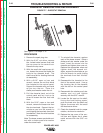
6. Install the bottom two end bracket thru-
bolts.
Note: The flat washer goes on the top right
hand thru-bolt for the green ground wire.
7. Tap the end bracket with the mallet as nec-
essary to position it. Tighten the bolts to
4.5 - 5.5 ft lbs. Alternate tightening in order
to pull the assembly together evenly. As
you tighten, look through the brush hous-
ing access door and watch the bearing to
judge end bracket movement and align-
ment.
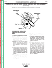
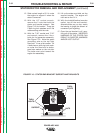
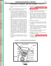
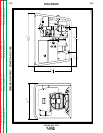
8. Check the rotor-stator air gap with the long
.010 feeler gauge. The measurement is
taken through the brush holder access
door; see Figure F12. Turn the engine with
the recoil starter rope slightly so that the
rotor “iron” is up to take the measurement.
(The rotor has two flat sides, which are not
measured for air gap.) Slide in the gauge.
Then rotate the shaft 180 degrees and
measure again. If the gauge does not
clear, loosen the four end bracket thru-
bolts, reposition the end bracket, retighten
the bolts, and recheck the air gap. Repeat
until the proper .010 minimum air gap is
achieved.
9. Tighten the end bracket support nuts and
lock washers. Remove the 2 X 4 engine
support.
10. Reinstall the brush holder assembly. Refer
to the topic “BRUSH REMOVAL AND
REPLACEMENT” in this section of the
manual.
11. Slide the control box back into place. Pull
the stator and ground wire up through.
12. Remove the control panel (2 screws) and
reconnect the output terminal leads (W1,
W2). Install a new cable tie to hold the
leads together. Reconnect the stator
wire/harness molex coupling. Install the 6
screws that hold the control panel to the
box.
13. Reconnect Lead #202C.
14. Lift the control box and screw in the rubber
mountings. Set the control box onto the
mountings.
15. Install the front left hand washer and nut
that anchors the control box to the stator
frame. Position the reactor and install the
remaining washers and nuts.
16. Check all terminal connections for clear-
ance, grounding, and tightness.
17. Replace the top cover to the control box
and tighten the 4 nuts.
18. Conduct the “RETEST AFTER REPAIR”
procedure, the following topic in this sec-
tion of the manual.
STATOR/ROTOR REMOVAL AND REPLACEMENT (continued)
Return to Section TOC Return to Section TOC Return to Section TOC Return to Section TOC
Return to Master TOC Return to Master TOC Return to Master TOC Return to Master TOC
FIGURE F.12 - CHECKING ROTOR-STATOR AIR GAP
ROTOR
STATOR
FEELER GAUGE