


Return to Section TOC Return to Section TOC Return to Section TOC Return to Section TOC
Return to Master TOC Return to Master TOC Return to Master TOC Return to Master TOC
E-3
THEORY OF OPERATION
E-3
POWER-ARC 4000
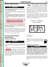
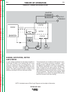
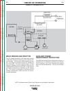
ROTOR FIELD FEEDBACK AND
AUXILIARY POWER
The AC voltage developed in the field winding is fed
to the full wave bridge. The DC output of the bridge
is filtered by the field capacitor and controlled by the
output rheostat.
This filtered and controlled feedback voltage is fed to
the rotor winding via the brush and slip ring configu-
ration. As the feedback voltage is increased or de-
creased, the outputs of the weld and auxiliary wind-
ings are likewise increased or decreased.
When full field voltage is applied to the rotor and the
engine is running at high speed (3700 RPM), a 230
VAC voltage is developed in the stator auxiliary wind-
ing. This winding is tapped to provide 115 VAC. The
two voltages (115 VAC and 230 VAC) are connected
to the appropriate receptacles and offer 4000 watts
(total) of AC power.
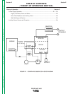
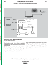
FIGURE E.3 – FIELD EXCITATION AND AUXILIARY POWER
NOTE: Unshaded areas of Block Logic Diagram are the subject of discussion
ENGINE
STATOR
STATOR
ROTOR
REACTOR
BRIDGE
CAPACITOR
RHEOSTAT
115 AND 230VAC
RECEPTACLES
OUTPUT
TERMINALS
ROTATION
MECHANICAL
SLIP
RINGS
ROTOR
MAGNETO