


Return to Section TOC Return to Section TOC Return to Section TOC Return to Section TOC
Return to Master TOC Return to Master TOC Return to Master TOC Return to Master TOC
F-31
TROUBLESHOOTING & REPAIR
F-31
POWER-ARC 4000
STATOR REMOVAL PROCEDURE
1. Remove engine spark plug wire to prevent
accidental kickback or starting.
2. With the 5/16” nut driver, remove the 4
sheet metal screws that hold the top cover
to the control box. Remove the top cover.
3. Remove the 4 1/2” nuts and washers that
anchor the control box to the stator frame.
Two of the nuts also anchor the reactor.
The reactor must be moved over to access
the front left hand nut anchoring the control
box. Be careful not to drop the washers
into the machine.
4. Lift up the control box and unscrew the 4
rubber mounts. Set the control box onto
the stator frame for the moment.
5. Pull apart the molex coupling that connects
the stator to the wiring harness.
6. With the slot head screw driver, remove the
6 sheet metal screws that hold the control
panel to the control box - 3 on each side.
You may need to use the 5/16” end wrench
on the engine side because of limited
clearance. Pull the panel away from the
control box.
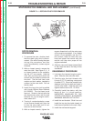
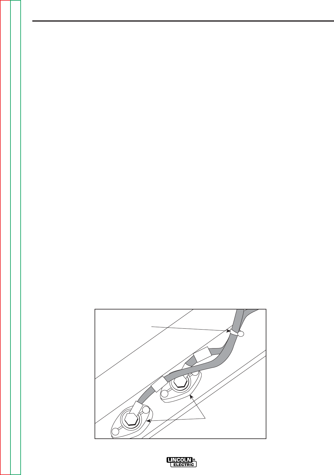
7. With the 9/16” open end wrench, remove
lead W2 (Black) from the output terminal.
See Figure F.9 for location. With the diag-
onal cutters, cut the cable tie that holds the
two output leads together. Pull lead W2
back out of the way; screw the bolt back
into the output terminal hole loosely for
reassembly. Set the control panel back on
the control box and hold it in place with 1
sheet metal screw in each side.
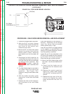
8. Remove the brush holder assembly. Open
the brush holder assembly cover. Squeeze
the 2 tabs and depress the cover at the top
with a screw driver or your fingernail. The
cover will drop open on its bottom hinge.
With the 1/4” nut driver, remove the 2
screws that hold the brush holder assem-
bly in place. With the needle nose pliers,
gently remove the black and the red wires.
Set the brush holder aside. Pull the wires
up into the control box.
9. Disconnect lead #202C from the engine
magneto, located next to the throttle
adjustment (See wiring diagram). This is
the single wire on the left side of the
machine, running from the engine to the
stator.
10. Disconnect lead W1 (Black) that connects
to the reactor lead. Replace the nut, split-
ring lock washer, and flat washer finger
tight on the bolt for reassembly.
11. Slide the control panel and box assembly
out of the machine cradle. Carefully pull
the wire leads down through the box as
you remove it. Note that the reactor is
loose inside the box and may slide around.
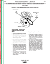
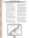
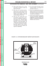
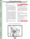
STATOR/ROTOR REMOVAL AND REPLACEMENT (continued)
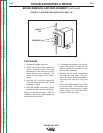
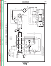
FIGURE F.9 - OUTPUT LEAD LOCATION
OUTPUT
TERMINALS
W1
W2
TIE WRAP