


Return to Section TOC Return to Section TOC Return to Section TOC Return to Section TOC
Return to Master TOC Return to Master TOC Return to Master TOC Return to Master TOC
F-28
TROUBLESHOOTING & REPAIR
F-28
POWER-ARC 4000
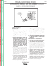
PROCEDURE - CAPACITOR
REMOVAL AND REPLACE-
MENT
1. Remove the engine spark plug wire.
2. With the 5/16” nut driver, remove
the sheet metal screws that hold the
top cover to the control box.
Remove the top cover.
3. With the 5/16” nut driver and wrench
remove the screws that hold the
control panel in place. Move the
panel aside as far as the leads will
allow.
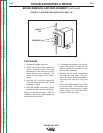
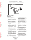
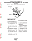
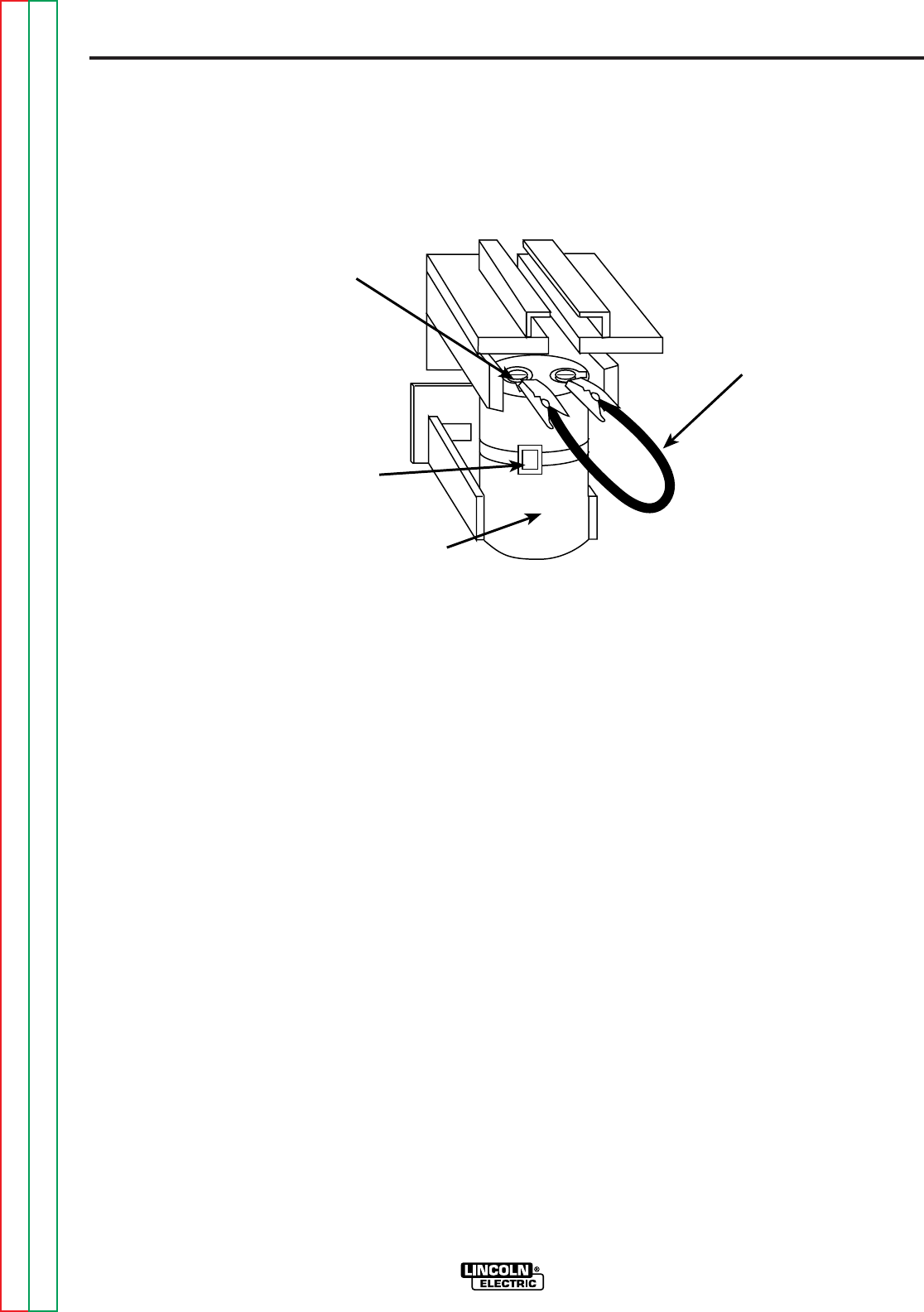
4. Discharge the field capacitor by
connecting the jumper wire clips on
the black and the red wire terminals
on the top of the capacitor. See
Figure F.8 for location. Leave the
clips on for at least 5 seconds, then
remove.
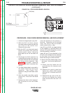
5. The capacitor is mounted in a mold-
ed plastic holder. To remove it, pull
out on the top of the holder, then
slide it upward.
6. Snap the capacitor out of the assem-
bly.
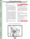
7. Loosen the two screws on the top of
the capacitor. Leads 202A and 202
attach to the positive (+) terminal.
Leads 201 and 201A attach to the
negative (-) terminal.
8. To replace the capacitor, reattach
the leads to their respective termi-
nals (202A and 202 to positive (+);
201 and 201A to negative (-) and
tighten the screws securely. Snap
the capacitor back into the molded
plastic holder and slide the holder
back into position in the panel.
Replace the control panel and top
cover of the control box and tighten
down the sheet metal screws with
the 5/16” nut driver.
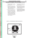
CAPACITOR AND/OR DIODE BRIDGE REMOVAL AND REPLACEMENT
(continued)
FIGURE F.8 - LOCATION AND DISCHARGING THE FIELD CAPACITOR
201
201A
(-)
202
202A
(+)
Attachment for
Attachment for
Jumper
Capacitor
Cable Tie