


INSTALLATION
A-4
POWER MIG 200
A-4
Return to Section TOC Return to Section TOC Return to Section TOC Return to Section TOC
Return to Master TOC Return to Master TOC Return to Master TOC Return to Master TOC
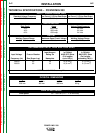
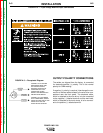
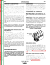
FIGURE A.1 — Dual Voltage Machine Input Connections
3. The 208/230 volt 60 Hz model POWER MIG is
shipped with a 7 ft. input cable and plug connected
to the welder.
The 230/460/575 volt 60 Hz model is not equipped
with an input cable or a plug.
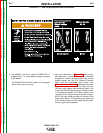
4. Using the instructions in Figure A.3, have a quali-
fied electrician connect a receptacle (Customer
Supplied) or cable to the input power lines and the
system ground per the U.S. National Electrical
Code and any applicable local codes. See
“Technical Specifications” at the beginning of this
chapter for proper wire sizes. For long runs over
100 feet, larger copper wires should be used. Fuse
the two hot lines with super lag type fuses as shown
in the following diagram. The center contact in the
receptacle is for the grounding connection. A green
wire in the input cable connects this contact to the
frame of the welder. This ensures proper grounding
of the welder frame when the welder plug is insert-
ed into a grounded receptacle.