


F-43
TROUBLESHOOTING AND REPAIR
F-43
POWER MIG 200
MAIN TRANSFORMER REPLACEMENT (Continued)
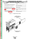
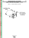
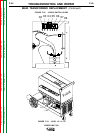
15. Carefully maneuver the main transformer
out the left side of the machine.
NOTE: Two people may be needed to maneu-
ver the main transformer out of the
machine.
REPLACEMENT
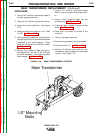
1. Carefully maneuver the new main trans-
former back into the machine and onto its
mounting studs.
2. Using a 1/2” nutdriver, mount the main trans-
former in its proper position.
3. Reconnect leads 118 and 121 previously
removed.
4. Using a 5/16” nutdriver, close the rear
access panel previously opened.
5. Reconnect lead X1 to the output diode
bridge rectifier.
6. Reconnect leads X8, X7, X6, X5, X4, X3, &
X2 previously removed from the switch
assembly.
7. Reconnect lead H1B and the other associat-
ed lead connected to the same terminal.
These leads are connected to the ON/OFF
switch.
8. Replace any necessary cable ties and wiring
harnesses.
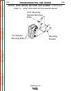
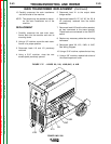
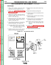
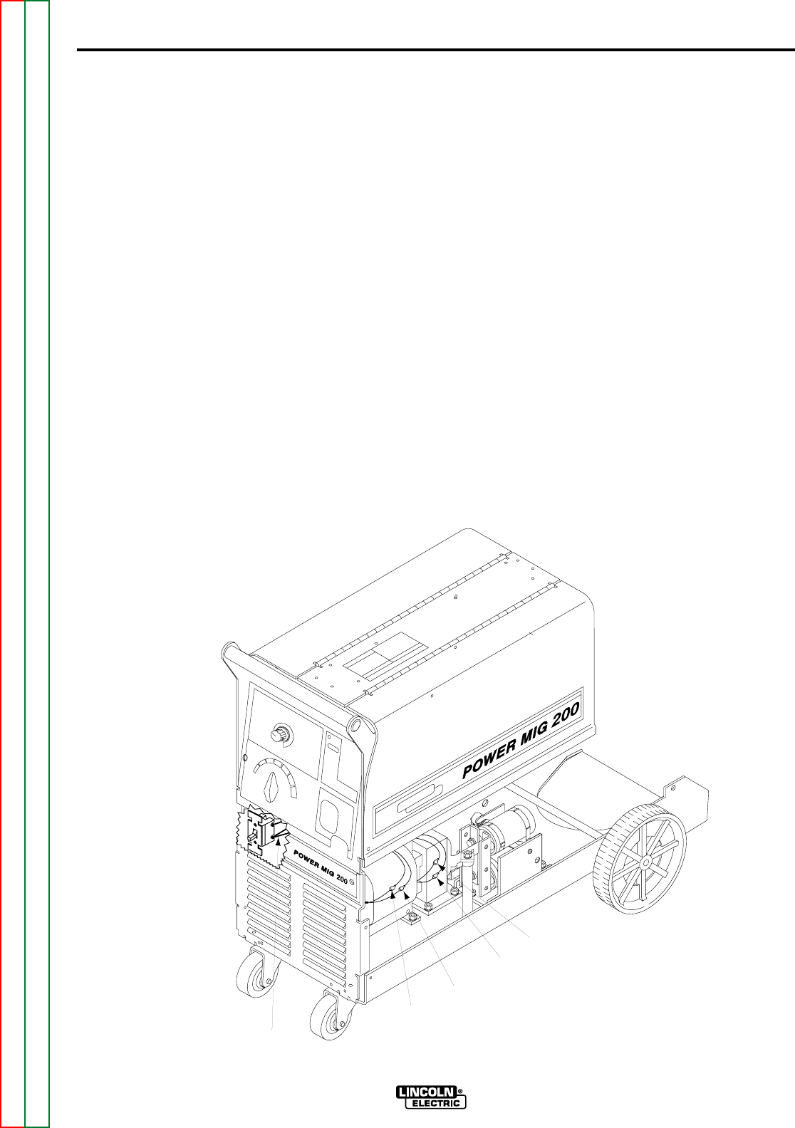
9. Reconnect leads X9, X10, 104B, & 104C.
See Wiring Diagram.
10. Using a 5/16” nutdriver, replace the tool tray.
11. Using a 3/8” nutdriver, replace both sides of
the case wraparound cover.
X10
X9
104B
104C
H1B
FIGURE F.17. - LEADS X9, X10, 104B,104C, & H1B
Return to Section TOC Return to Section TOC Return to Section TOC Return to Section TOC
Return to Master TOC Return to Master TOC Return to Master TOC Return to Master TOC