


F-50
TROUBLESHOOTING AND REPAIR
F-50
POWER MIG 200
OUTPUT CONTACTOR REPLACEMENT (Continued)
PROCEDURE
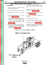
1. Using a 5/16” nutdriver, remove the three
screws securing the tool tray.
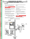
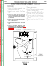
2. Locate the output contactor. See Figure
F.23.
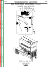
3. Using a 7/16” wrench, label and remove the
two thick black leads at the top of the output
contactor. Note lead and washer placement
for reassembly.
4. Remove lead 107A and note lead place-
ment. See Figure F.23.
5. Remove leads 106B and 106C. See Figure
F.23.
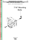
6. Using a 7/16” wrench, remove the three
mounting bolts from the output contactor.
Note washer positions for replacement. See
Figure F.24.
7. Replace output contactor.
8. Using a 7/16” wrench, mount the new output
contactor in its proper location.
9. Reconnect leads 106B, 106C, & 107A to
their proper terminals. See Wiring Diagram.
10. Reconnect the two thick black leads previ-
ously removed from the top of the output
contactor.
11. Replace the tool tray using a 5/16” nutdriv-
er.
107A
106C
106B
Output
Contactor
FIGURE F.23. - OUTPUT CONTACTOR LEADS
Return to Section TOC Return to Section TOC Return to Section TOC Return to Section TOC
Return to Master TOC Return to Master TOC Return to Master TOC Return to Master TOC