


F-3
TROUBLESHOOTING AND REPAIR
F-3
POWER MIG 200
Sometimes machine failures appear to be due
to PC board failures. These problems can
sometimes be traced to poor electrical con-
nections. To avoid problems when trou-
bleshooting and replacing PC boards, please
use the following procedure:
1. Determine to the best of your technical
ability that the PC board is the most
likely component causing the failure
symptom.
2. Check for loose connections at the PC
board to assure that the PC board is
properly connected.
3. If the problem persists, replace the
suspect PC board using standard
practices to avoid static electrical
damage and electrical shock. Read the
warning inside the static resistant bag
and perform the following procedures:
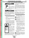
PC board can be
damaged by static
electricity.
- Remove your body’s
static charge before
opening the static-
shielding bag. Wear an
anti-static wrist strap. For
safety, use a 1 Meg ohm
resistive cord connected
to a grounded part of the
equipment frame.
- If you don’t have a wrist
strap, touch an un-
painted, grounded, part of the equipment
frame. Keep touching the frame to prevent
static build-up. Be sure not to touch any
electrically live parts at the same time.
ELECTRIC SHOCK
can kill.
•
Have an electrician
install and service this
equipment. Turn the input
power OFF at the
- Tools which come in contact with the PC
board must be either conductive, anti-static or
static-dissipative.
- Remove the PC board from the static-shield-
ing bag and place it directly into the equip-
ment. Don’t set the PC board on or near paper,
plastic or cloth which could have a static
charge. If the PC board can’t be installed
immediately, put it back in the static-shielding
bag.
- If the PC board uses protective shorting
jumpers, don’t remove them until installation is
complete.
- If you return a PC board to The Lincoln
Electric Company for credit, it must be in the
static-shielding bag. This will prevent further
damage and allow proper failure analysis.
4. Test the machine to determine if the
failure symptom has been corrected by
the replacement PC board.
NOTE: It is desirable to have a spare
(known good) PC board available for PC
board troubleshooting.
NOTE
: Allow the machine to heat up so that
all electrical components can reach their
operating temperature.
5. Remove the replacement PC board and
substitute it with the original PC board
to recreate the original problem.
a. If the original problem does not
reappear by substituting the original
board, then the PC board was not
the problem. Continue to look for
bad connections in the control wiring
harness, junction blocks, and
terminal strips.
b. If the original problem is recreated by
the substitution of the original board,
then the PC board was the problem.
Reinstall the replacement PC board
and test the machine.
6. Always indicate that this procedure was
followed when warranty reports are to
be submitted.
NOTE
: Following this procedure and writing
on the warranty report, “INSTALLED AND
SWITCHED PC BOARDS TO VERIFY PROB-
LEM,” will help avoid denial of legitimate PC
board warranty claims.
PC BOARD TROUBLESHOOTING PROCEDURES
ATTENTION
Static-Sensitive
Devices
Handle only at
Static-Safe
Workstations
WARNING
CAUTION
fuse box before working on equipment. Do
not touch electrically hot parts.
Return to Section TOC Return to Section TOC Return to Section TOC Return to Section TOC
Return to Master TOC Return to Master TOC Return to Master TOC Return to Master TOC