


F-42
TROUBLESHOOTING AND REPAIR
F-42
POWER MIG 200
MAIN TRANSFORMER REPLACEMENT (Continued)
PROCEDURE
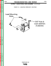
1. Using a 3/8” nutdriver, remove both sides of
the case wraparound cover.
2. Using a 5/16” nutdriver, remove the tool tray.
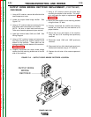
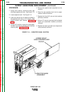
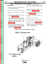
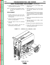
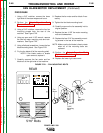
3. Locate the main transformer. See Figure
F.16.
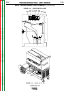
4. Label and disconnect leads X9, X10, 104B,
& 104C. See Figure F.17.
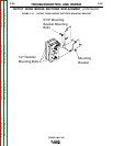
5. Using a flathead screwdriver, Label and dis-
connect lead H1B and other associated lead
connected to the same terminal. These
leads are connected to the ON/OFF switch.
See Figure F.17.
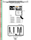
6. Using a 7/16” nutdriver, Label and discon-
nect leads X8, X7, X6, X5, X4, X3, & X2 from
the switch assembly. Note washer position
upon removal. See Figure F.18.
7. Using a 1/2” nutdriver, label and remove
lead X1 from the output diode bridge rectifi-
er.
8. Using a 5/16” Nutdriver, open the rear
access panel. See Figure F.20.
9. Disconnect lead 118 from the rear access
panel. See Figure F.21.
10. Feed lead 118 toward the inside of the
machine.
11. Cut any necessary cable ties.
12. Remove any necessary wiring harnesses.
13. Disconnect lead 121. See Figure F.19.
14. Using a 1/2” nutdriver, remove the four main
transformer mounting bolts and associated
washers. See Figure F.16.
FIGURE F.16. - MAIN TRANSFORMER LOCATION
Main Transformer
1/2" Mounting
Bolts
Return to Section TOC Return to Section TOC Return to Section TOC Return to Section TOC
Return to Master TOC Return to Master TOC Return to Master TOC Return to Master TOC