


THEORY OF OPERATION
E-4E-4
POWER MIG 200
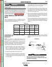
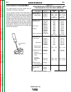
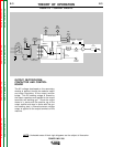
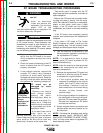
CONTROL BOARD, GUN
TRIGGER AND WIRE DRIVE
MOTOR
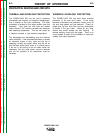
When the control board receives an activation
command from the trigger circuit the control
board activates the gas solenoid, output
contactor, and the wire drive motor. The control
board monitors the motor’s tach feedback
signals and compares these to the wire speed
control setting. The proper armature voltage is
then applied to the wire drive motor. The drive
motor speed is thus controlled which in turn
regulates the electrode wire feed speed through
the gun.
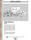
Two thermostats are included in the trigger
circuitry. If either of these thermostats would
“open”, the trigger circuit would be interrupted
and the machine’s output would be disabled.
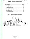
FIGURE E.4 – OPTIONAL CIRCUITS.
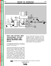
NOTE: Unshaded areas of block logic diagrams are the subject of discussion.
Return to Section TOC Return to Section TOC Return to Section TOC Return to Section TOC
Return to Master TOC Return to Master TOC Return to Master TOC Return to Master TOC
LINE
SWITCH
RECONNECT
PANEL
FAN
MOTOR
RECTIFIER
DIODE
BRIDGE
CONTROL BOARD
GAS
SOLENOID
WIRE
SPEED
CONTROL
WIRE
DRIVE
MOTOR
TACH
FEEDBACK
GUN TRIGGER
+
-
OUTPUT DIODE
BRIDGE
+
-
NEGATIVE
TERMINAL
CONTACTOR
CONTACTOR
CONTROL
TAP SELECTOR
SWITCH
OUTPUT
CHOKE
POSITIVE
TERMINAL
TRANSFORMER
THERMOSTAT
OUTPUT BRIDGE
THERMOSTAT
28 VAC
MAIN
TRANSFORMER
OUTPUT
CAPACITORS
GUN
ASSEMBLY