


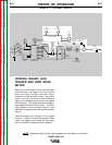
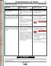
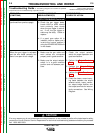
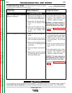
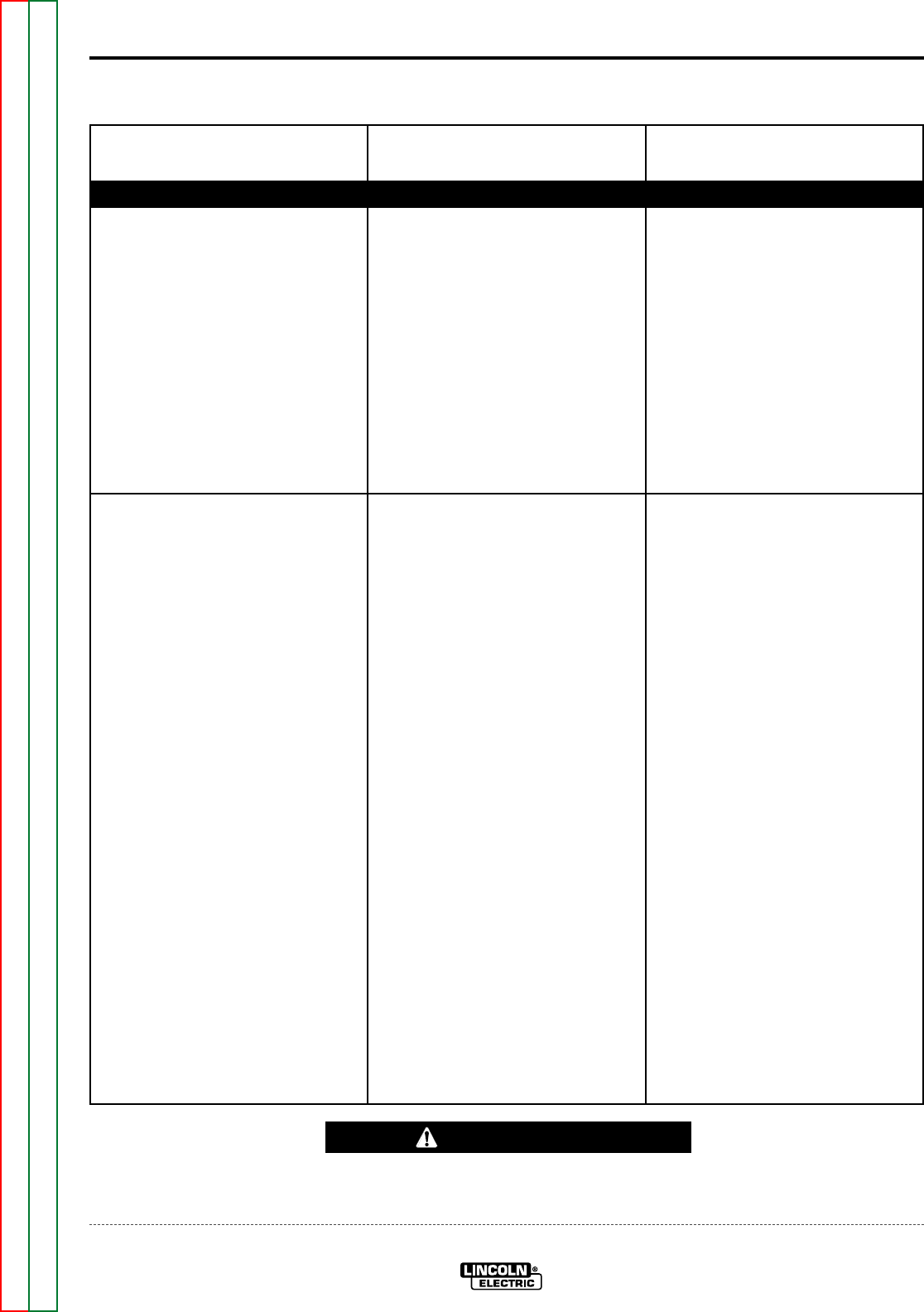
When the gun trigger is activated
and the wire feeds normally, but
there is no open circuit voltage.
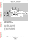
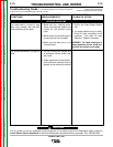
OUTPUT PROBLEMS (Continued)
TROUBLESHOOTING AND REPAIR
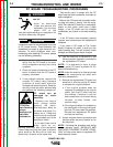
Observe Safety Guidelines
detailed in the beginning of this manual.
Troubleshooting Guide – See Wiring Diagrams for location of specified
components and for troubleshooting of specific circuits.
F-5F-5
POWER MIG 200
PROBLEMS
(SYMPTOMS)
POSSIBLE AREAS OF
MISADJUSTMENT(S)
RECOMMENDED
COURSE OF ACTION
(continued from previous page) 3. Check the gun trigger leads.
Leads #324 to #325 should
have continuity (zero ohms)
when the gun trigger is activat-
ed. If not, the gun trigger or
cable may be faulty. Check or
replace.
4. If a spool gum option kit is
installed, check to make sure it
is set to the “normal” position if
using the POWER MIG 200 built
in wire feeder.
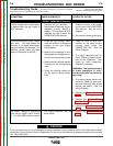
1. Make sure the gun cable and
work cables are connected
properly and in good condition.
2. Make sure the output selector
switch is in a good condition
position and not between posi-
tions.
1. Check the output selector
switch for proper operation and
good connections.
2. Perform the Output Contactor
Test.
3. Perform the Output Bridge
Rectifier Test.
4. Perform the Main Transformer
Test.
5. Check the heavy current carry-
ing leads between the output
selector switch, output contac-
tor, output bridge rectifier, and
the output terminals for loose or
faulty connections. See Wiring
Diagram.
If for any reason you do not understand the test procedures or are unable to perform the tests/repairs safely,
contact the Lincoln Electric Service Department for technical troubleshooting assistance before you proceed.
Call 1-800-833-9353.
CAUTION
Return to Section TOC Return to Section TOC Return to Section TOC Return to Section TOC
Return to Master TOC Return to Master TOC Return to Master TOC Return to Master TOC