


TROUBLESHOOTING AND REPAIR
F-14F-14
POWER MIG 200
Return to Section TOC Return to Section TOC Return to Section TOC Return to Section TOC
Return to Master TOC Return to Master TOC Return to Master TOC Return to Master TOC
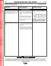
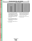
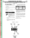
INPUT VOLTAGE TEST POINTS
EXPECTED VOLTAGE READING
11.9-13.0 VAC
14.1-15.2 VAC
16.2-17.5 VAC
18.4-19.7 VAC
20.5-22.0 VAC
22.7-24.2 VAC
24.8-26.5 VAC
26.9-28.8 VAC
X1-X2
X1-X3
X1-X4
X1-X5
X1-X6
X1-X7
X1-X8
X9-X10
230 VAC
230 VAC
230 VAC
230 VAC
230 VAC
230 VAC
230 VAC
230 VAC
TABLE F.1. Test Points
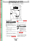
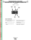
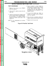
12. If ALL the voltages tested are incorrect
or missing, test for correct nameplate
input voltage between the H1 lead at the
ON/OFF POWER SWITCH to H2 or H3
at the reconnect panel. Voltage tested
will vary depending on input voltage con-
nection. See wiring diagram for test
point locations.
A. If the input voltage test is incorrect,
check for loose or broken leads between
the reconnect panel and the ON/OFF
POWER SWITCH.
B. Test the ON/OFF POWER SWITCH for
proper operation.
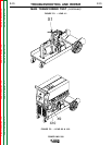
13. If the correct nameplate voltage is being
applied to the main transformer and one
or more of the secondary voltages are
missing or are incorrect, the main trans-
former may be faulty. Replace.
14. When test is complete, replace tool tray,
case sides and top.