


TROUBLESHOOTING AND REPAIR
F-22F-22
POWER MIG 200
TEST PROCEDURE
1. Remove the input power to the POWER
MIG 200 machine.
2. Using the 5/16” Nutdriver, remove the
tool tray.
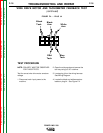
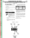
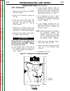
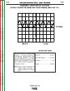
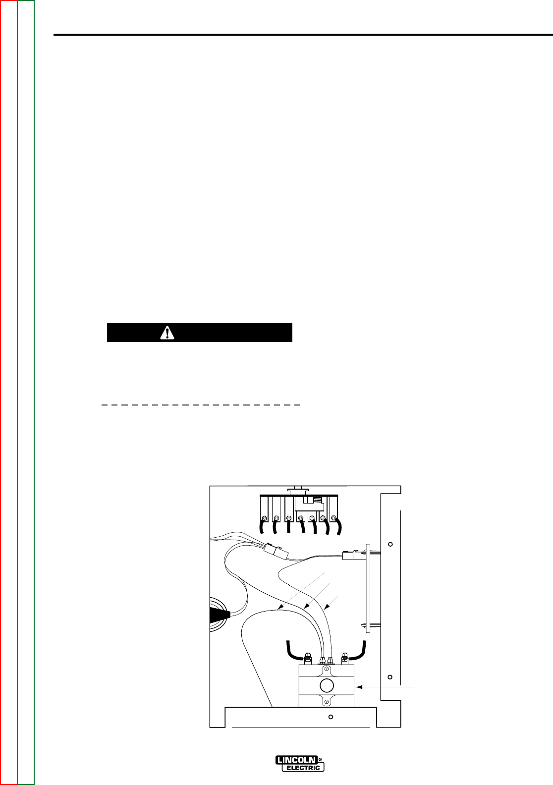
3. Locate and remove leads 106B, 106C
and 107A from the contactor coil
terminals. See Figure F.7. See the
Wiring Diagram.
4. Using the 7/16” wrench, remove one
lead from the contactors large terminals.
See Figure F.7. See the Wiring Diagram.
5. Carefully apply 12 VDC to the contactor
coil leads. (small terminals)
Do not leave the 12 VDC applied to the
contactor coil for a prolonged period of
time (15 seconds maximum). Damage
to contactor may result.
6. If the contactor does not activate when
the 12VDC is applied, the contactor is
faulty. Replace.
7. If the contactor activates when the
12VDC is applied, check the resistance
between the two large terminals with
the contactor activated. The resistance
should be very low (0 to 1 ohm).
8. If the resistance is “high” or “open”
between the two large terminals when
the contactor is activated, the contactor
is faulty. Replace.
9. If the contactor activates and the
resistance between the terminals is low
when the 12 VDC is applied, the
contactor is good
NOTE: When the contactor is not activated,
the resistance between the
terminals should be very high
(infinite). If the resistance is always
low, the contacts are “stuck” and
the contactor is faulty. Replace.
10. When the test is complete, replace
leads 106B, 106C and 107A.
11. Replace the lead previously removed
from one of the contactor large
terminals.
12. Replace the tool tray.
Return to Section TOC Return to Section TOC Return to Section TOC Return to Section TOC
Return to Master TOC Return to Master TOC Return to Master TOC Return to Master TOC
107A
106C
106B
Output
Contactor
Figure F.7. Contactor Terminals and Leads
CAUTION
CONTACTOR TEST (Continued)