


ACCESSORIES
C-3C-3
POWER MIG 200
Return to Section TOC Return to Section TOC Return to Section TOC Return to Section TOC
Return to Master TOC Return to Master TOC Return to Master TOC Return to Master TOC
MAKING A WELD WITH THE SPOOL GUN
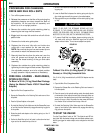
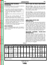
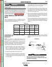
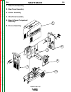
ADAPTER KIT AND SPOOL GUN
INSTALLED
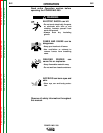
In either toggle switch position, closing either gun
trigger will cause the electrode of both guns to be
electrically “HOT”. Be sure unused gun is posi-
tioned so electrode or tip will not contact metal
case or other metal common to work.
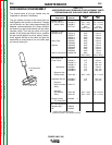
1. Setting spool gun selector switch to the “Normal”
position and pulling the trigger for the built-in feeder
gun.
• Disables spool gun operation and spool gun gas
solenoid valve.
• Closing feeder gun trigger starts feeder gun
welding and makes both electrodes electrically
“HOT”.
2. Setting spool gun selector switch to the Spool Gun
Position and pulling SPOOL GUN Trigger.
• Disables built-in feeder gun operation and
machine gas solenoid valve.
• Enables spool gun operation and spool gun gas
solenoid valve.
• Closing spool gun trigger starts spool gun weld-
ing and makes both
electrodes electrically
“HOT”.
3. Operation with POWER MIG 200:
• Turn the POWER MIG-200 input power ON.
• Adjusting the voltage tap control will increase or
decrease your welding voltage.
• Adjusting the wire speed control on the spool
gun will increase or decrease the spool gun wire
feed speed. NOTE: Adjusting the wire feed
speed control on the Power Mig Panel has no
affect on the spool gun’s wire feed speed.
4. Refer to the procedure decal on the Power Mig for
initial aluminum settings. Make a test weld to deter-
mine the final settings.
CAUTION
5. To return to normal POWER MIG 200 welding,
release the spool gun trigger set spool gun selector
switch to normal and reset feeder gun voltage pro-
cedure setting if necessary.