


A-5
GUN AND CABLE INSTALLATION
A Magnum 300 gun and 15Ft.(4.6m) cable
(12Ft.(3.7m) for Codes 11000 and below) are provid-
ed with the POWER MIG 300. A Magnum cable liner
for .035-.045" (0.9-1.2 mm) electrode and contact tips
for .035” (0.9mm) and .045” (1.2mm) are included for
15Ft..
Turn the welder power switch off before installing
gun and cable.
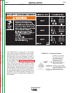
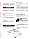
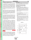
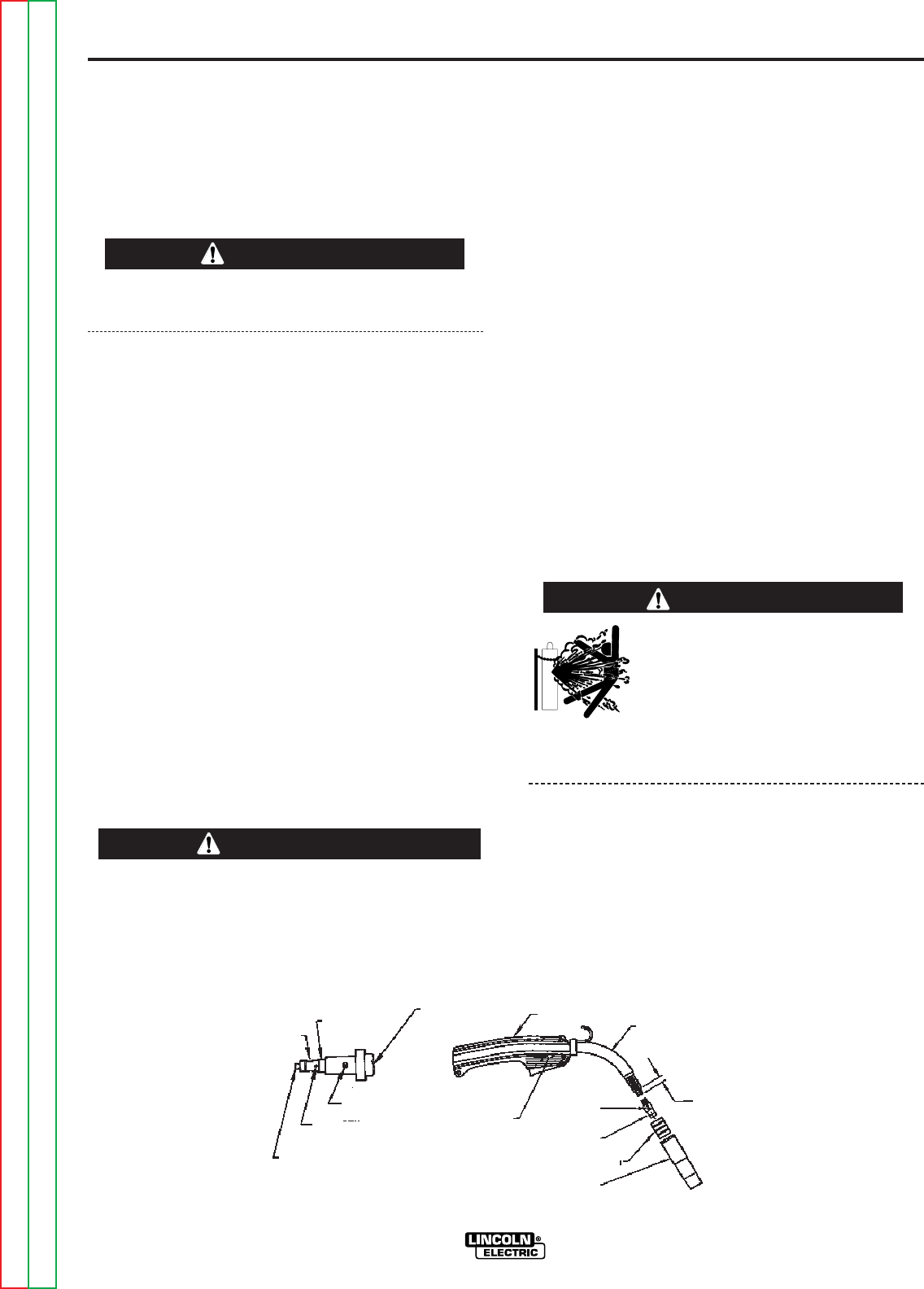
LINER INSTALLATION AND TRIMMING
INSTRUCTION (SEE FIGURE A.3)
1. Remove the gas nozzle.
2. Remove the gas diffuser from the gun tube. If gas
diffuser contains a small set screw, loosen the set
screw.
3. Lay gun and cable out straight on a flat surface.
Loosen set screw of the connector on the back end
of the gun.
4. Insert the untrimmed Liner into the back end of the
gun.
5. Seat Liner bushing into back of gun. Secure Liner
by tightening set screw. Do not install the gas dif-
fuser at this time.
6. Lay the cable straight and trim Liner to 9/16”.
Remove burrs.
7. Secure the gas diffuser into the tube.
8. Tighten the set screw against the Liner.
This screw should only be gently tightened. Over
tightening will split or collapse the liner and cause
poor wire feeding.
------------------------------------------------------------------------
WARNING
A-5
INSTALLATION
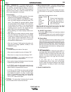
GUN & CABLE ASSEMBLY INSTALLED
INTO THE POWER MIG
1. Unscrew knurled screw on the drive unit front end
(inside wire feed compartment) until tip of screw no
longer protrudes into gun opening as seen from
front of machine.
2. Insert the male end of gun cable into the female
casting through opening in front panel. Make sure
connector is fully inserted and tighten knurled
screw.
3. Connect the gun trigger connector from the gun
and cable to the mating receptacle inside the com-
partment located above the gun connection made
in step 2 above. Make sure that the key ways are
aligned, insert and tighten retaining ring.
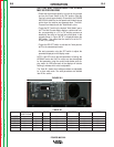
SHIELDING GAS
(For Gas Metal Arc Welding Processes)
Customer must provide cylinder of appropriate type
shielding gas for the process being used.
A gas flow regulator, for CO
2
or Argon blend gas, and
an inlet gas hose are factory provided with the
POWER MIG 300.
Install shielding gas supply as follows:
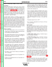
1. Set gas cylinder on rear platform of POWER MIG
300. Hook chain in place to secure cylinder to rear
of welder.
2. Remove the cylinder cap. Inspect the cylinder
valves and regulator for damaged threads, dirt,
dust, oil or grease. Remove dust and dirt with a
clean cloth.
WARNING
CYLINDER may explode if
damaged.
• Gas under pressure is explosive. Always
keep gas cylinders in an upright position
and always keep chained to undercarriage
or stationary support. See American
National Standard Z-49.1, “Safety in
Welding and Cutting” published by the
American Welding Society.
GUN HANDLE
SET SCREW
SET SCREW
INSULATION TUBE
FEEDR END
CABLE HANDLE
CLAMPING SCREW
GUN TUBE
9/16 (14.3mm)
GAS DIFFUSER
NOZZLE INSULATION
GAS NOZZLE
MOLDED GAS PLUG
LINER ASSEMBLY (LINER BUSHING TO BE SEATED
TIGHT AGIANST BRASS CABLE CONNECTOR)
BRASS CABLE
CONNECTOR
LINER TRIM
LENGTH
FIGURE A.3
CAUTION
POWER MIG 300
Return to Section TOC Return to Section TOC Return to Section TOC Return to Section TOC
Return to Master TOC Return to Master TOC Return to Master TOC Return to Master TOC