


Return to Section TOC Return to Section TOC Return to Section TOC Return to Section TOC
Return to Master TOC Return to Master TOC Return to Master TOC Return to Master TOC
TROUBLESHOOTING & REPAIR
F-34 F-34
POWER MIG 300
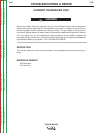
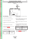
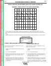
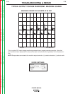
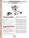
This is a typical DC output voltage waveform generated from a properly operating machine. Note that
each vertical division represents 20 volts and that each horizontal division represents 2.00 milliseconds in
time.
NOTE: Scope probes connected at the machine output terminals: (+) probe to electrode, (-) probe to work.
SCOPE SETTINGS
Volts/Div.....................20V/Div.
Horizontal Sweep..2.5 ms/Div.
Coupling.............................DC
Trigger.........................Internal
OSCILLOSCOPE WAVEFORMS MUST BE TAKEN IN MODE 201
NORMAL OPEN CIRCUIT VOLTAGE WAVEFORM
20.0 V
2.0 MS/DIV
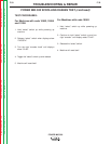
CODES 10562 AND BELOW
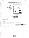
Power Mig 300 in mode 201. Mode 201 is a con-
stant current test mode.
1. Toggle and hold the Mode Select switch in the up
position.
2. Turn on the Power Mig 300.
3. Rotate the right output knob, while still holding the
Mode Select switch up, until the display reads
“ALL nodE”.
4. Release the Mode Select switch and toggle the
Mode Set switch until the MSPlll panel reads 201.
Disengage the idler arm on the wire drive so no
wire will feed.
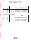
CODES 10952 AND UP
Power Mig 300 in mode 201. Mode 201 is a con-
stant current test mode.
1. Toggle and hold the Mode Select switch in the up
position.
2. Turn on the Power Mig 300.
3. Once the display reads “Pres Spin” release the
mode select switch. Rotate the output knob until
the display reads “ALL nodE”.
4. Toggle the Mode Select switch once and wait for
the machine to reset, then toggle the MODE SET
switch until the MSPlll panel reads 201. Disengage
the idler arm on the wire drive so no wire will feed.